
Patient-specific tray for orthodontic vibrational force management

a technology for vibrational force management and orthodontics, which is applied in the field of patient-specific trays for orthodontic vibrational force management, can solve the problems of inability to provide the selective control of providing the needed stimulation, adverse outcomes, and generic trays in the current products do not allow this level of control, and achieves a high peak load and minimal force

Active Publication Date: 2022-04-26
CREATIVE ESP INC
View PDF28 Cites 3 Cited by
  • Summary
  • Abstract
  • Description
  • Claims
  • Application Information

AI Technical Summary

Benefits of technology

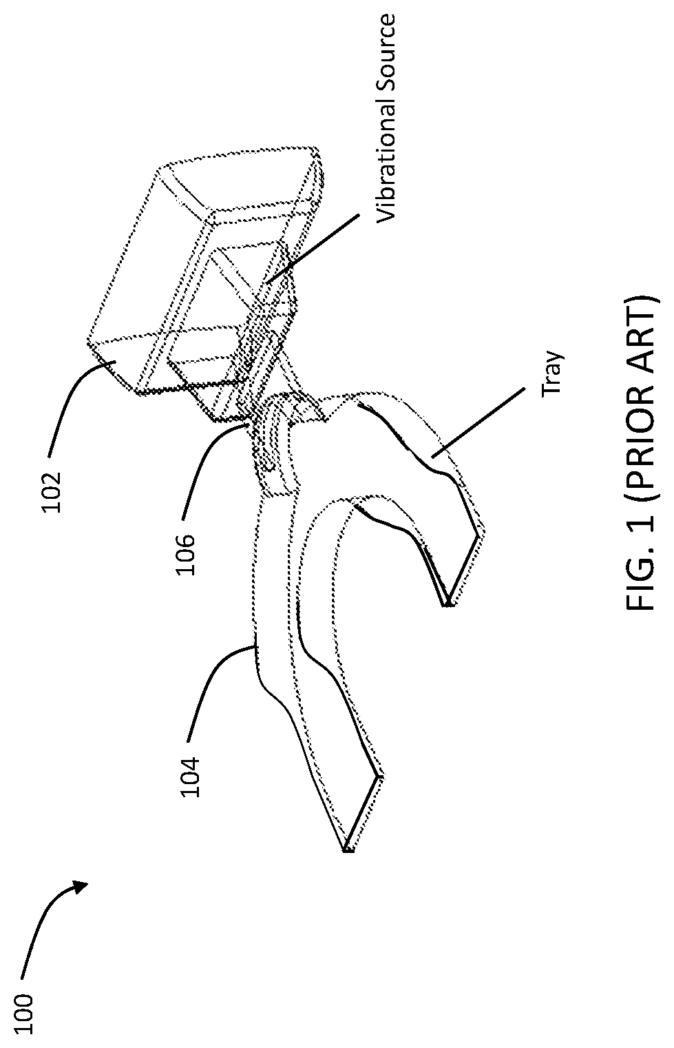
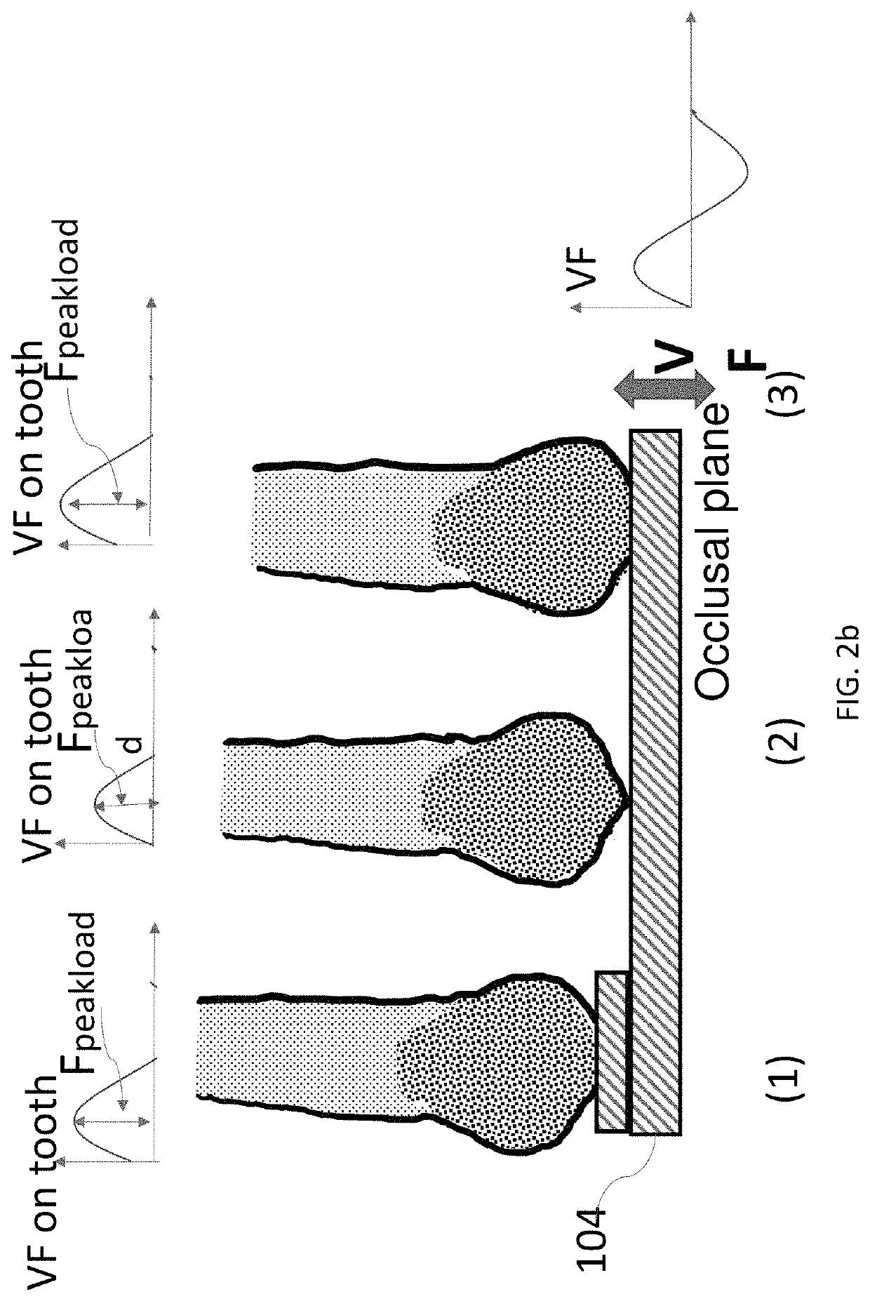
The patent describes a treatment that uses a vibrational tool to stimulate teeth. The tool is attached to a tray that is placed in the mouth of the patient. The patient is instructed to bite down on the tray with minimal force to hold it in position. The vibrational force is applied through the tray to the teeth. The force is greatest on the tooth with the most interference, and it is less or not at all on the tooth with the least interference. The treatment is effective because it allows the dentist to selectively stimulate specific teeth within a predetermined intensity range. The patient-specific tray ensures that only the intended teeth are stimulated.

Problems solved by technology

The stimulation outside the range may either have no effect if the stimulation is too low or damage the tissue if the stimulation is too high, causing adverse outcomes.
However, the devices of the prior art do not provide the selective control for providing the needed stimulation.
The generic trays in the current products do not allow this level of control.
The major issue of the current products is that they cannot guarantee the delivery of the correct stimulations to the specified teeth to be moved.
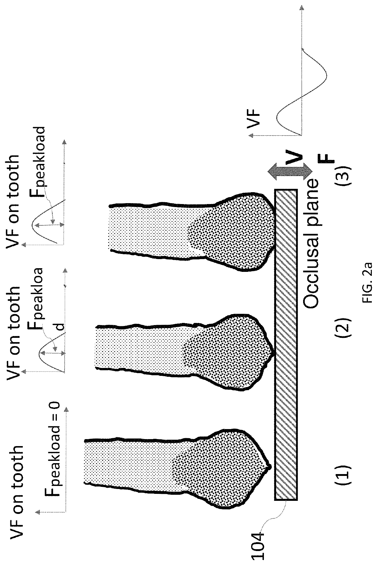
Second, the level of the vibrational force intensity on the tooth depends on the level of vibrational force delivered from the vibrational source and the pre-load on the tooth when biting on the tray.
The current vibrational device cannot guarantee delivery of the desired stimulations to the teeth due to the following three main reasons: 1) inability to guarantee delivery of the vibrational force to the specified tooth / teeth; and 2) inability to control the stimulation intensity on the targeted tooth / teeth.
The first aspect is due to lack of control of contact between the teeth to be moved and the tray.
It does not adapt to patients' teeth occlusal profile.
Naturally, the occlusal profile of the teeth are not uniform.
With the current device, the intensity is also not controllable because, due to uneven occlusal tooth profile.
Therefore, for a flat tray, stimulations on these teeth are not controllable, which result in inability to guarantee delivering the desired stimulation to the specific teeth.
Without the adequate stimulation, the clinical treatment intention will not be realized, causing inconsistent treatment outcomes.
This is another factor that results in inconsistency of the treatment.
Because of these, the existing vibrational force (VF) devices do not guarantee delivery of the stimulation nor control the level of stimulation.
Inconsistent treatment effects have been widely reported, which resulted in uncertainty of its efficacy.

Method used


Image

  • Patient-specific tray for orthodontic vibrational force management
  • Patient-specific tray for orthodontic vibrational force management
  • Patient-specific tray for orthodontic vibrational force management

Examples


Embodiment Construction

[0021]In the following detailed description, reference is made to be accompanying drawings which form a part hereof, and in which is shown by way of illustration specific embodiments in which the present disclosure is practiced. These embodiments are described in sufficient detail to enable those skilled in the art to practice the present disclosure, and it is to be understood that other embodiments can be utilized and that structural changes can be made without departing from the scope of the present disclosure. Therefore, the following detailed description is not to be taken in a limiting sense, and the scope of the present disclosure is defined by the appended claims and their equivalents.

[0022]Reference throughout this specification to “one embodiment,”“an embodiment,” or similar language means that a particular feature, structure, or characteristic described in connection with the embodiment is included in at least one embodiment of the present disclosure. Appearances of the ph...


PUM


Abstract

A device for accelerating tooth movement under orthodontic treatment is disclosed. The device includes a vibrational source and a patient-specific tray. The device applies vibrational forces with prescribed frequency and intensity to the teeth under orthodontic treatment with traditional appliances, such as bracket-wire system or aligner. The patient-specific tray ensures the vibrational stimulations on the teeth to be moved. The level of stimulation intensity can be controlled by varying the preload on each of the teeth based on the clinician's prescription. The tray can be further modified to ensure continuous delivery of the desired vibrational forces on the teeth when they move during the treatment.

Description

CROSS-REFERENCE TO RELATED APPLICATIONS[0001]The present patent application is related to and claims the priority benefit of U.S. Provisional Patent Application Ser. No. 62 / 726,533 filed 4 Sep. 2018, the contents of which are hereby incorporated by reference in its entirety into the present disclosure.FIELD OF DISCLOSURE[0002]The present disclosure relates to a device for supplementing existing orthodontic treatments to effectively accelerate tooth movement in orthodontic treatments using vibrational force.BACKGROUND OF THE DISCLOSURE[0003]In orthodontic treatment, clinicians develop treatment plans that include moving certain teeth and keeping others stationary or minimally moved. Orthodontic appliances, such as bracket-wire system and aligner, are commonly used to execute the treatment. To shorten the treatment time, accelerating the movement of the teeth to be moved and securing the anchorage tooth to be stationary are in high demand, which benefits both clinicians and patients.[...

Claims


Application Information

Patent Timeline
Patent Type & Authority Patents(United States)
IPC IPC(8): A61C7/00A61C7/36
CPCA61C7/008A61C7/36
Inventor CHEN, JIE
Owner CREATIVE ESP INC
Learn More