Pressing sensor

a sensor and pressing technology, applied in piezoelectric/electrostrictive/magnetostrictive devices, instruments, computing, etc., can solve the problems of different operation surface warps and may not detect pressing operations, and achieve high sensitivity and efficient detection

Active Publication Date: 2022-05-03
MURATA MFG CO LTD
View PDF10 Cites 2 Cited by
  • Summary
  • Abstract
  • Description
  • Claims
  • Application Information

AI Technical Summary

Benefits of technology

[0007]The piezoelectric film most efficiently detects stretching and contraction in the direction of 45 degrees with respect to the uniaxial direction (drawing direction). In addition, potentials of the same polarity are generated at the locations where the electrodes face each other obliquely to the drawing direction. The pressing sensor of the present invention has a high sensitivity by having the first electrode and the second electrode arranged so as to face each other obliquely to the drawing direction. Further, even when the center of the operation surface is pressed or the end of the operation surface is pressed, the potentials of the same polarity are acquired at the locations facing each other obliquely to the drawing direction, therefore, the pressing sensor of the present invention can detect the pressing regardless of the pressing position.

Problems solved by technology

A problem with this proposed solution is that the operation surface warps differently depending on whether the operation surface is pressed, in plan view, in the vicinity of the center or at the end.
Therefore, depending on the pressing position, the pressing operation may not be detected.

Method used


Image

  • Pressing sensor
  • Pressing sensor
  • Pressing sensor

Examples


Embodiment Construction

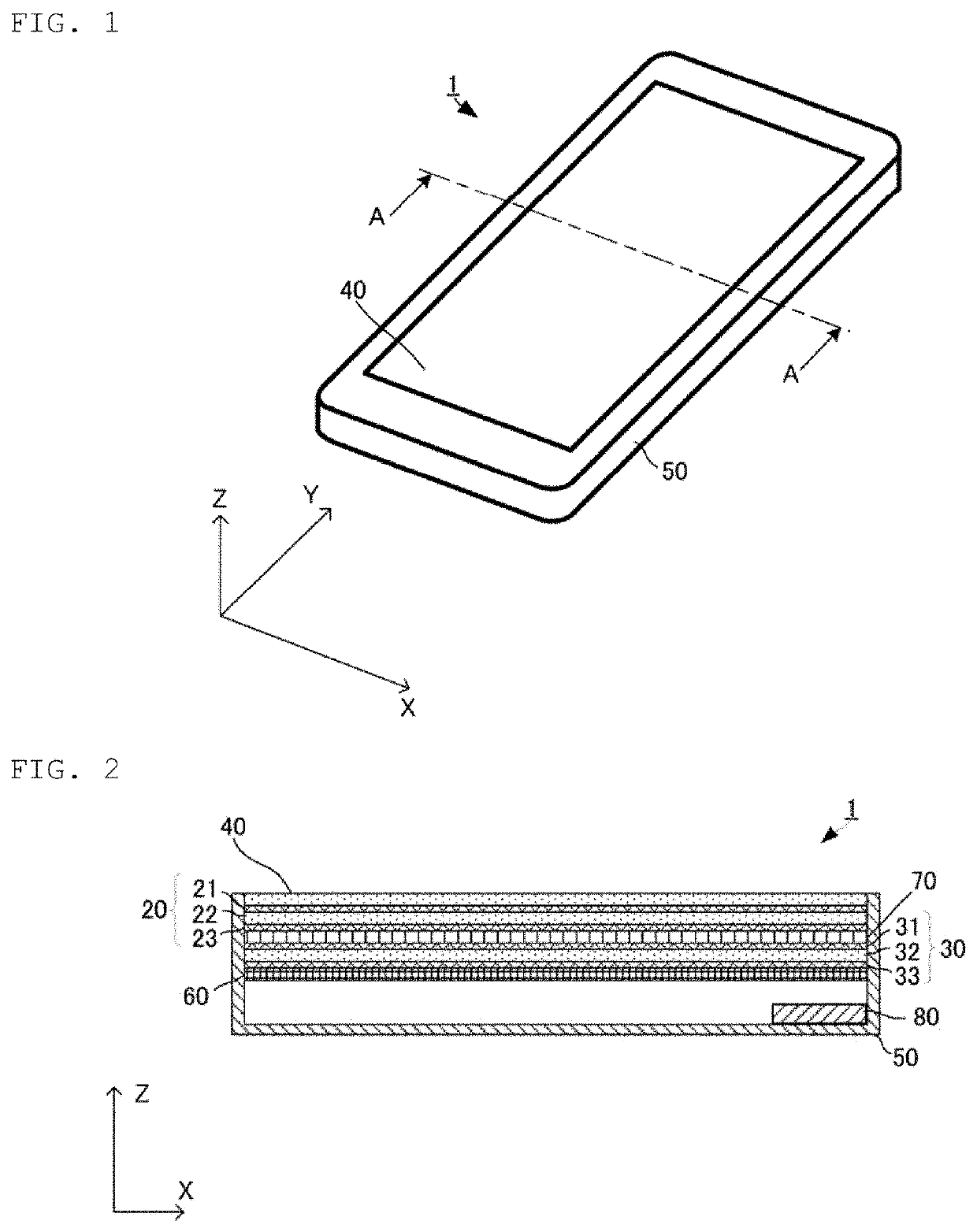
[0019]Referring now to the drawings, wherein like numerals indicate like elements, exemplary pressing sensors in accordance with the present invention, FIGS. 1 and 2 show an exemplary pressing sensor 30 used as part of a display device 1. The display device 1 can be an information processing device such as a smartphone or a tablet. In the preferred embodiment, the display device has a generally rectangular parallelepiped shape with a thickness lying in the Z direction, a width lying in the X direction and a length lying in the Y direction.

[0020]The display device includes a housing 50 having a generally rectangular parallelepiped shape and a surface or touch panel 40 having a flat, planar shape and being arranged in an opening on the upper face of the housing 50. The upper surface of the surface panel 40 functions as an operation surface on which a user can perform touch and pressing operations using, for example, his or her finger or a pointer device such as a pen.

[0021]As best sho...


PUM

PropertyMeasurementUnit
angleaaaaaaaaaa
piezoelectricaaaaaaaaaa
lengthaaaaaaaaaa

Abstract

A pressing sensor includes a piezoelectric film and first and second detection electrodes. The piezoelectric film has a chiral polymer drawn at least in a uniaxial direction, and has a first main surface and a second main surface. The first and second detection electrodes are arranged on at least one of the first and second main surfaces. The first and second detection electrodes are arranged so as to face each other obliquely to the uniaxial direction.

Description

CROSS REFERENCE TO RELATED APPLICATIONS[0001]The present application is a continuation of International application No. PCT / JP2020 / 015863, filed Apr. 8, 2020, which claims priority to Japanese Patent Application No. 2019-089621, filed May 10, 2019, the entire contents of each of which are incorporated herein by reference.FIELD OF THE INVENTION[0002]The present invention relates to a pressing sensor that detects a pressing operation.BACKGROUND OF THE INVENTION[0003]Japanese Patent No. 6132076 (Patent Document 1) discloses a pressing sensor that detects a pressing operation. As explained therein, when the entire circumference of an operation surface is fixed to a housing, the potential generated in a piezoelectric element may be reversed with respect to the warping of the operation surface depending on a pressing position, causing the output to be reduced or reversed. Patent Document 1 suppresses the reverse potential from being generated by ensuring that the shape of the lateral sect...

Claims


Application Information

Patent Timeline
Patent Type & Authority Patents(United States)
IPC IPC(8): G06F3/044H01L41/08H01L41/113G06F3/041
CPCG06F3/044G06F3/0448H01L41/0805H01L41/1132G06F3/0445G06F3/0446G06F3/0414G06F2203/04105H10N30/878H10N30/87H10N30/302H10N30/857H10N30/1051
Inventor KITADA, HIROAKI
Owner MURATA MFG CO LTD
Why Eureka
Try Eureka