Filter circuit and radio-frequency module

a filter circuit and radio frequency module technology, applied in the field of filter circuits and radio frequency modules, can solve the problems of achieve the effect of decreasing the number of required filters and increasing the size of the apparatus

Active Publication Date: 2022-05-03
MURATA MFG CO LTD
View PDF9 Cites 0 Cited by
  • Summary
  • Abstract
  • Description
  • Claims
  • Application Information

AI Technical Summary

Benefits of technology

[0008]In order to resolve the above problem, it is an object of the present disclosure to provide a filter circuit that is less likely to cause an increase in size of the apparatus even if the number of communication bands is increased and a radio-frequency module including such a filter circuit.
[0010]According to the present disclosure, filtering of the first communication signal in the first communication band and the second communication signal in the second communication band is performed by the single first band pass filter. Accordingly, the number of required filters is decreased, compared with a case in which filtering of the first communication signal and the second communication signal is performed by separate filters.
[0011]Consequently, it is possible to achieve the filter circuit that is less likely to cause an increase in size of the apparatus even if the number of communication bands is increased and the radio-frequency module including such a filter circuit.

Problems solved by technology

However, since the front-end circuit in Patent Document 1 includes the filters for the respective communication bands, the number of required filters is increased with the increasing number of communication bands to cause a problem of increasing the size of the apparatus.

Method used


Image

  • Filter circuit and radio-frequency module
  • Filter circuit and radio-frequency module
  • Filter circuit and radio-frequency module

Examples


first embodiment

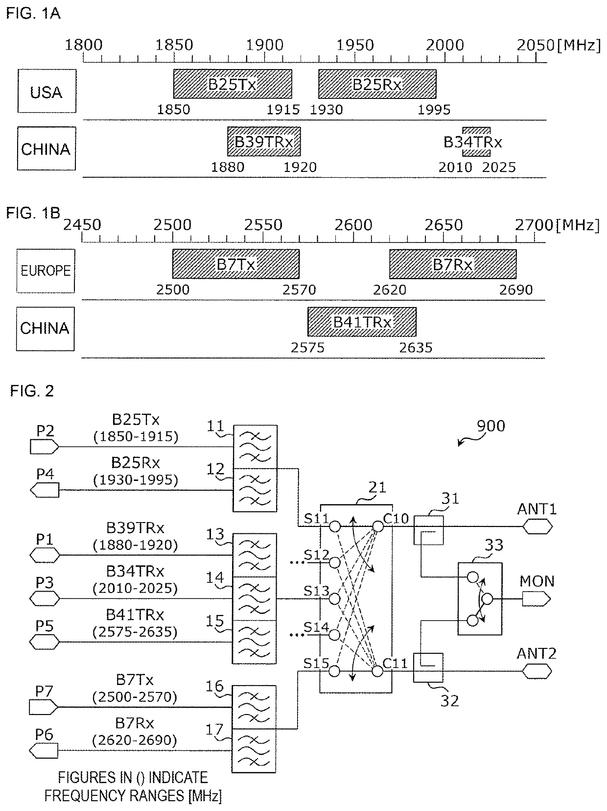
[0023]A filter circuit according to a first embodiment is a filter circuit for performing multiband communication using multiple communication bands. A filter circuit for performing the multiband communication using five communication bands of Bands 7, 25, 34, 39 and 41 defined in the E-UTRA will now be described as a specific example.

[0024]FIG. 1A and FIG. 1B are diagrams indicating the frequency ranges of the five communication bands. The five communication bands include the communication bands the duplex mode of which is Frequency Division Duplex (FDD) and the communication bands the duplex mode of which is Time Division Duplex (TDD). In the FDD, transmission and reception are concurrently performed using a transmission frequency band and a reception frequency band that are different from each other. In the TDD, transmission and reception are performed using one transmission-reception frequency range in time division.

[0025]The duplex mode of Band 7 is the FDD and is operated in E...

second embodiment

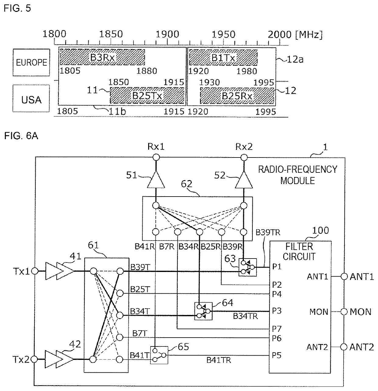
[0083]A radio-frequency module according to a second embodiment will now be described, giving an example of a radio-frequency module that includes the filter circuit according to the first embodiment and that supports carrier aggregation communication in which communication is performed by concurrently using two communication bands.

[0084]FIG. 6A, FIG. 6B, and FIG. 6C are block diagrams illustrating an example of the functional configuration of the radio-frequency module according to the second embodiment and illustrate different connection states of the same radio-frequency module. As illustrated in FIG. 6A, FIG. 6B, and FIG. 6C, a radio-frequency module 1 includes power amplifiers 41 and 42, low noise amplifiers 51 and 52, switches 61 to 65, and the filter circuit 100. The filter circuit 100 is the filter circuit 100 illustrated in FIG. 4.

[0085]The switch 61 switches the connection between an output end of each of the power amplifiers 41 and 42 and any one path of transmission sign...


PUM


Abstract

A filter circuit includes a first switch circuit that exclusively connects a first common terminal to either of a first selection terminal and a second selection terminal; a first signal terminal that is connected to the first selection terminal and that is for communicating a first communication signal belonging to a first frequency range, which is a frequency range of a first communication band; a second signal terminal that is connected to the second selection terminal and that is for communicating a second communication signal belonging to a second frequency range, which is the frequency range of a second communication band and which is at least partially overlapped with the first frequency range; and a first band pass filter one end of which is connected to the first common terminal and which uses both the first frequency range and the second frequency range as pass bands.

Description

[0001]This is a continuation of International Application No. PCT / JP2018 / 033975 filed on Sep. 13, 2018 which claims priority from Japanese Patent Application No. 2017-181571 filed on Sep. 21, 2017. The contents of these applications are incorporated herein by reference in their entireties.BACKGROUND OF THE DISCLOSUREField of the Disclosure[0002]The present disclosure relates to filter circuits and radio-frequency modules. In particular, the present disclosure relates to a filter circuit and a radio-frequency module for performing multiband communication using multiple frequency ranges.Description of the Related Art[0003]Communication apparatuses are in widespread use, which perform the multiband communication using multiple communication bands.[0004]Evolved Universal Terrestrial Radio Access (E-UTRA) designed by Third Generation Partnership Project (3GPP) is exemplified as a communication standard defining the multiband communication. The E-UTRA is also referred to as Long Term Evol...

Claims


Application Information

Patent Timeline
Patent Type & Authority Patents(United States)
IPC IPC(8): H04J1/04H04B1/52H04B1/56H03K17/16
CPCH04J1/045H03K17/164H04B1/52H04B1/56H03D2200/0058H04B1/0057H04B1/006
Inventor TAHARA, KENJIMATSUMOTO, SHOU
Owner MURATA MFG CO LTD
Why Eureka
Try Eureka