Supercharge Your Innovation With Domain-Expert AI Agents!

Image processing apparatus, image forming apparatus, image processing method, and storage medium

a technology of image processing and forming apparatus, which is applied in the field of image processing apparatus, image forming apparatus, image processing method, and storage medium, and can solve the problems of reducing the sharpness of the output image, affecting the image more easily, and heavy processing load of the output imag

Active Publication Date: 2022-05-03
CANON KK
View PDF12 Cites 0 Cited by
  • Summary
  • Abstract
  • Description
  • Claims
  • Application Information

AI Technical Summary

Benefits of technology

The present invention is an image processing apparatus that is capable of generating a sharpness recovery amount to recover degradation of a spatial frequency response from a target image. It also has a line width correction unit that is capable of performing line width correction processing for the target image based on the sharpness recovery amount. This means that the line width correction unit will correct the line width of a pixel in the image based on the sign of a pixel that has a large absolute value for the sharpness recovery amount. The patent text provides a technical effect of improving image quality through enhancements in sharpness and clarity.

Problems solved by technology

Further, the relationship between the latent image potential on the photosensitive body and the amount of toner to be attached as a developer in the developing process is nonlinear and in addition, the more the contrast of the latent image potential is reduced, the more easily the image is affected.
Because of this, fine image data whose image width is narrow and whose contrast of the latent image potential is easily reduced has such a problem that thinning and crushing of a line occur in the image forming process, and therefore, sharpness of an output image is reduced.
However, the technique disclosed in Japanese Patent Laid-Open No. 2000-36912 or Japanese Patent Laid-Open No. 2009-105943 requires processing to detect the line width in image data and there is such a problem that the processing load thereof is heavy.
Further, for example, in the case where those techniques are applied to an input image including a complex-shaped character, line drawing, or the like, there is a case where a processing-target edge portion or a line width for determining a correction amount is extracted erroneously, and therefore, there is also such a problem that the line width is not controlled appropriately and improvement of sharpness is not sufficient.

Method used


Image

  • Image processing apparatus, image forming apparatus, image processing method, and storage medium
  • Image processing apparatus, image forming apparatus, image processing method, and storage medium
  • Image processing apparatus, image forming apparatus, image processing method, and storage medium

Examples


first embodiment

(Configuration of Image Forming System)

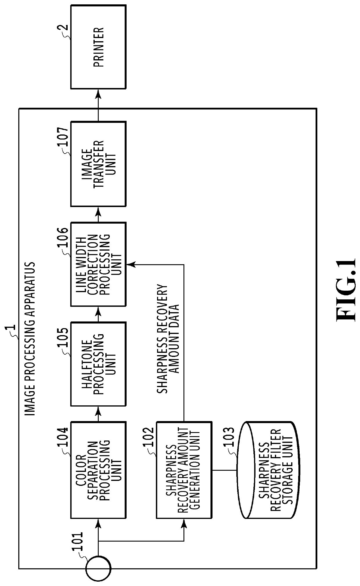
[0025]FIG. 1 is a block diagram showing a configuration of an image processing apparatus according to a first embodiment of the present invention. An image processing apparatus 1 configures an image forming system by connecting to a printer 2, which is an image output unit, by a printer interface or a circuit. The image processing apparatus 1 is implemented by, for example, a printer driver and the like installed in a general personal computer. Further, in that case, each unit of the image processing apparatus 1 to be explained in the following is implemented by the computer executing a predetermined program. Furthermore, as another configuration, for example, one in which the printer 2 includes the image processing apparatus 1 may be made.

[0026]The image processing apparatus 1 acquires printing-target image data from an image input terminal 101. Image data is RGB image data made up of 8-bit R (red), G (green), and B (blue). A sharpness recover...

second embodiment

[0086]In the above-described embodiment, the example is explained in which the value generated by using the sharpness recovery filter is used as the sharpness recovery amount as it is, but it may also be possible to add the sharpness recovery amount to the input image and to use the sharpness recovery amount corresponding to that which exceeds the upper limit value of the input image. That is, it may also be possible to perform the sharpness recovery processing by the normal filter processing until the upper limit value of the input image is reached and to improve sharpness by the line width correction processing for that which exceeds the upper limit value. Further, the average value of the sharpness recovery amounts of the processing point is calculated as a correction amount, but the calculation method of a correction amount is not limited to this. For example, the absolute value of the sharpness recovery amount may be used as a correction amount or it may also be possible to fin...

third embodiment

[0088]In the first embodiment described above, the example is explained in which the value generated by using the sharpness recovery filter is used as the sharpness recovery amount as it is. However, there is a case where it is better to correct the line width also in the case where the absolute values of the positive and negative sharpness recovery amounts at the edge portion are the same. For example, depending on the printer engine and the image design, there is a case where a black line (line on which a color material is placed) is printed thick and a solid-white line is printed thin even though the line width is the same on the digital image. Because of this, it is appropriate to give priority to reproduction of a solid-white line and to reduce the density of the edge portion of a black line.

[0089]Consequently, in a third embodiment, a configuration is explained in which the sharpness recovery amount is used after being modified so as to give priority to reproduction of a solid...


PUM


Abstract

The image processing apparatus of the present invention includes: a generation unit configured to generate a sharpness recovery amount for recovering degradation of a spatial frequency response from a target image; and a line width correction unit configured to perform line width correction processing for the target image based on the sharpness recovery amount, and the line width correction unit corrects a line width in accordance with a sign of a pixel whose absolute value of the sharpness recovery amount is large in a case where signs of the sharpness recovery amounts reverse between adjacent pixels of the target image.

Description

BACKGROUND OF THE INVENTIONField of the Invention[0001]The present invention relates to an image processing apparatus for improving sharpness of an image, an image forming apparatus, an image processing method, and a storage medium.Description of the Related Art[0002]Conventionally, an electrophotographic image forming apparatus is known, such as a laser beam printer and an LED printer, which forms an electrostatic latent image by irradiating a photosensitive body with light beams based on image data and develops the electrostatic latent image by attaching a developer thereto.[0003]In the image forming apparatus such as this, in the light beam irradiation process or in the electrostatic latent image forming process, the image is dulled, and therefore, the contrast of a latent image potential formed on the photosensitive body is reduced. Further, the relationship between the latent image potential on the photosensitive body and the amount of toner to be attached as a developer in the...

Claims


Application Information

Patent Timeline
Patent Type & Authority Patents(United States)
IPC IPC(8): H04N1/409G06T5/00G03G15/01G06T5/30G03G15/00G06K15/02
CPCH04N1/409G03G15/01G03G15/5087G06K15/1873G06K15/1881G06T5/003G06T5/30H04N1/4092G06T5/73
Inventor OTANI, RYOSUKEISHIKAWA, HISASHI
Owner CANON KK
Features
  • R&D
  • Intellectual Property
  • Life Sciences
  • Materials
  • Tech Scout
  • Unparalleled Data Quality
  • Higher Quality Content
  • 60% Fewer Hallucinations
Learn More