Encoding device and encoding method, and decoding device and decoding method
a technology of coding device and coding method, which is applied in the field of coding device, coding method, decoding device and decoding method, can solve the problems of inability to improve coding efficiency, difficult to regularly assign view id, and the arrangement of cameras cannot be recognized based on view id, so as to improve the coding efficiency of an image of a plurality of viewpoints
- Summary
- Abstract
- Description
- Claims
- Application Information
AI Technical Summary
Benefits of technology
Problems solved by technology
Method used
Image

Examples
first embodiment
[0072](Configuration Example of Encoding Device According to First Embodiment)
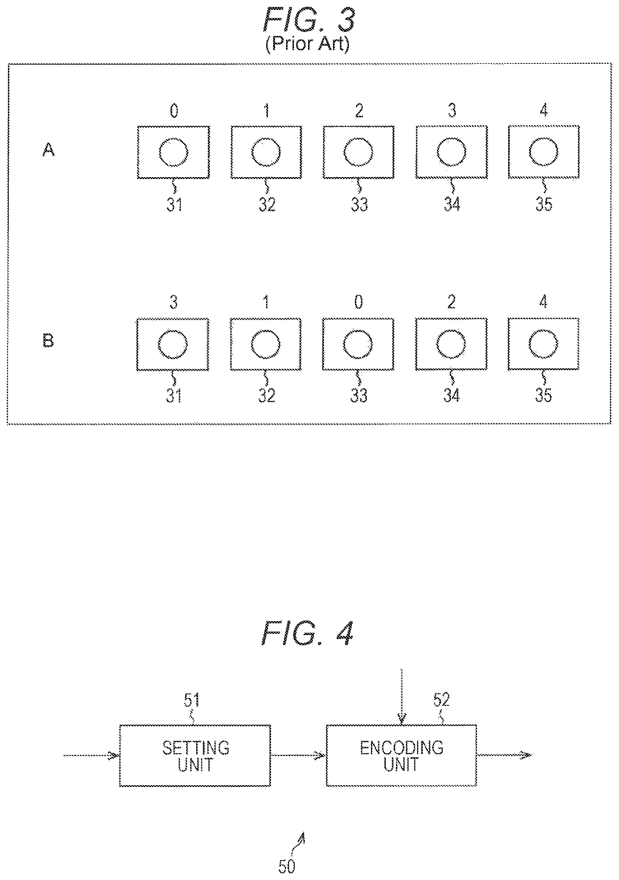
[0073]FIG. 4 is a block diagram that illustrates an example of the configuration of an encoding device of a first embodiment to which the present technology is applied.
[0074]An encoding device 50 illustrated in FIG. 4 is configured by a setting unit 51 and an encoding unit 52. The encoding device 50 generates a coded stream by coding an image (hereinafter, referred to as a multi-viewpoint image) of a plurality of viewpoints photographed by cameras as a plurality of imaging units that are aligned in parallel in a one-dimension arrangement by using a 3D coding system and transmits the generated coded stream.
[0075]More specifically, the setting unit 51 of the encoding device 50 sets an SPS (Sequence Parameter Set), a PPS (Picture Parameter Set), and the like. In addition, the setting unit 51 sequentially assigns view IDs (viewpoint identification information) from the viewpoint of a camera disposed at the end...
second embodiment
[0230](Configuration Example of Encoding Device According to Second Embodiment)
[0231]FIG. 21 is a block diagram that illustrates an example of the configuration of an encoding device of a second embodiment to which the present technology is applied.
[0232]An encoding device 400 illustrated in FIG. 21 is configured by a setting unit 401 and an encoding unit 402. The encoding device 400 transmits a VPS with a list flag used for identifying that the list registration process of FIG. 16 is performed and a scaling flag used for identifying that the parallax scaling process is performed being included therein instead of the order reliability flag.
[0233]More specifically, the setting unit 401 of the encoding device 400, similar to the setting unit 51 illustrated in FIG. 4, sets an SPS, a PPS, and the like. In addition, the setting unit 401, similar to the setting unit 51, sequentially assigns view IDs from a viewpoint of a camera arranged at the end among a plurality of cameras aligned in a...
third embodiment
[0279](Configuration Example of Encoding Device According to Third Embodiment)
[0280]FIG. 29 is a block diagram that illustrates an example of the configuration of an encoding device of a third embodiment to which the present technology is applied.
[0281]An encoding device 600 illustrated in FIG. 29 is configured by a setting unit 601 and an encoding unit 602. The encoding device 600 transmits a VPS with coefficient information representing the coefficient tb and the coefficient td in the parallax scaling process being included therein instead of the scaling flag.
[0282]More specifically, the setting unit 601 of the encoding device 600, similar to the setting unit 51 illustrated in FIG. 4, sets an SPS, a PPS, and the like. In addition, the setting unit 601, similar to the setting unit 51, sequentially assigns view IDs from a viewpoint of a camera arranged at the end among a plurality of cameras aligned in a one-dimensional arrangement. Furthermore, the setting unit 601 generates the li...
PUM
 Abstract
Description
Claims
Application Information
 - R&D
- Intellectual Property
- Life Sciences
- Materials
- Tech Scout
- Unparalleled Data Quality
- Higher Quality Content
- 60% Fewer Hallucinations
Browse by: Latest US Patents, China's latest patents, Technical Efficacy Thesaurus, Application Domain, Technology Topic, Popular Technical Reports.
© 2025 PatSnap. All rights reserved.Legal|Privacy policy|Modern Slavery Act Transparency Statement|Sitemap|About US| Contact US: help@patsnap.com