Circuit module and power supply chip module

a technology of circuit modules and power supply chips, applied in the field of circuit modules, can solve the problems of increased production costs and difficulty in widening the wiring pattern in the direction, and achieve the effect of sufficient effective sectional area of wiring, sufficient wiring width, and sufficient wiring width

Active Publication Date: 2022-05-17
AISIN CORP
View PDF17 Cites 0 Cited by
  • Summary
  • Abstract
  • Description
  • Claims
  • Application Information

AI Technical Summary

Benefits of technology

[0010]According to this configuration, the power supply output terminal group arranged side by side in the outermost peripheral row and the power supply destination can be connected by the surface wiring formed on the mounting surface of the board on which the power supply chip module is mounted. In addition, since the power supply output terminal groups arranged side by side in the outermost peripheral row are adjacent to each other in the circumferential direction of the connection terminals arranged in a rectangular annular shape, it is possible to provide the surface layer wiring having a sufficient wiring width in the direction along the arrangement direction and in which a wiring impedance is suppressed. Since the power supply output terminal group arranged in the inner peripheral row is at least partially overlapped with the power output terminal group arranged in the outermost peripheral row when viewed in the direction orthogonal to the arrangement direction, it is difficult for the power supply output terminal group arranged in the inner peripheral row to connect to the power supply destination by the surface wiring on the mounting surface. However, with the wiring provided on another wiring layer other than the surface wiring on the mounting surface of the board, the power supply output terminal group arranged in the inner peripheral row can be appropriately connected to the power supply destination. That is, since a sufficient wiring width can be secured in the surface direction of the board on which the power supply chip module is mounted, and a sufficient effective sectional area of the wiring can be ensured, there is no need to expand the effective sectional area of the wiring in the thickness direction of the board. Thus, it is possible to suppress an increase in the wiring layer (inner wiring layer) of the board. As described above, according to the present configuration, it is possible to appropriately connect the power supply source and the power supply destination while suppressing an increase in the wiring layer of the mounting board.

Problems solved by technology

However, when the power supply terminals corresponding to one power supply are arranged side by side from the center of the power supply IC (202) toward the outer peripheral side, it is difficult to widen the wiring pattern in the direction along the mounting board surface in order to maintain insulation from the terminals adjacent in the circumferential direction.
For the multilayer board, there is a possibility that the production cost increases as the number of layers increases.

Method used


Image

  • Circuit module and power supply chip module
  • Circuit module and power supply chip module
  • Circuit module and power supply chip module

Examples


Embodiment Construction

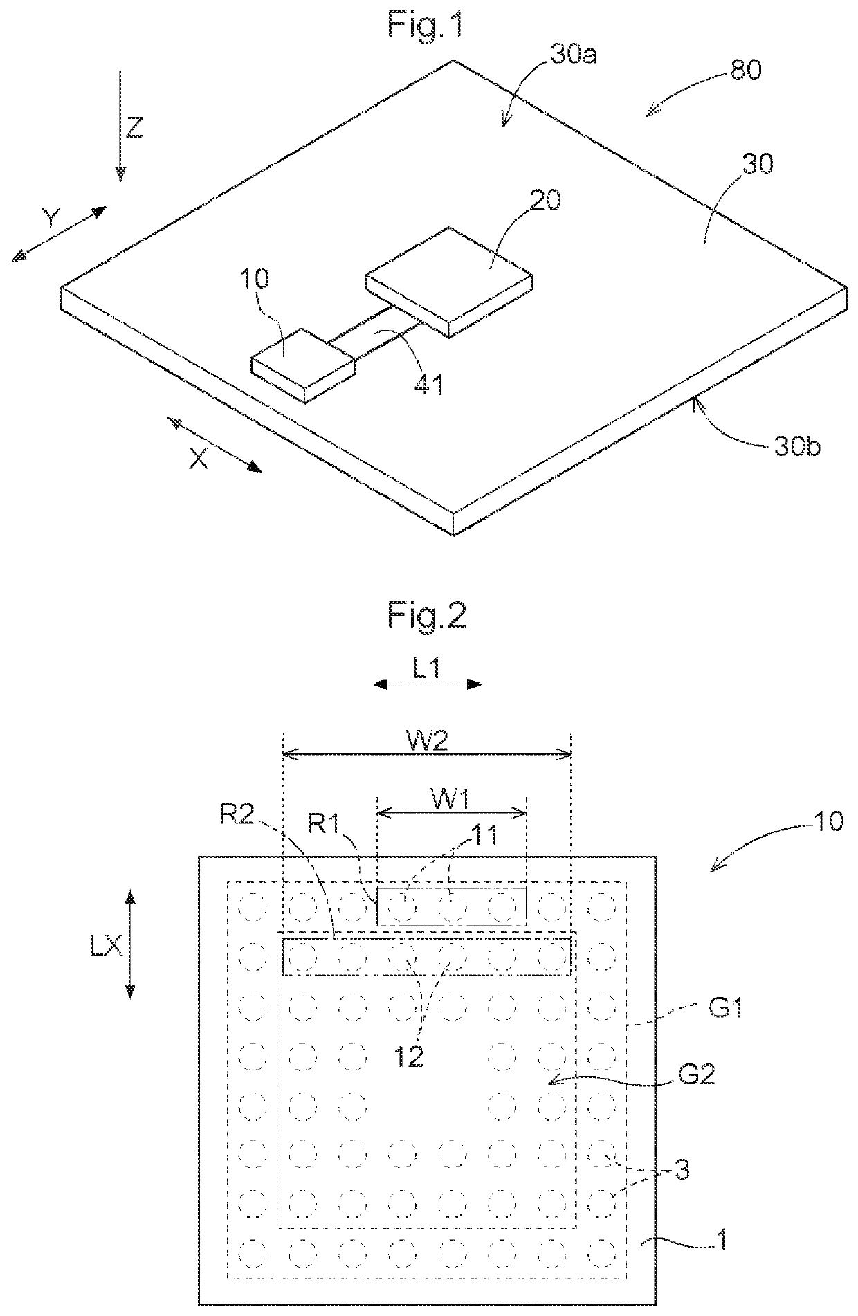
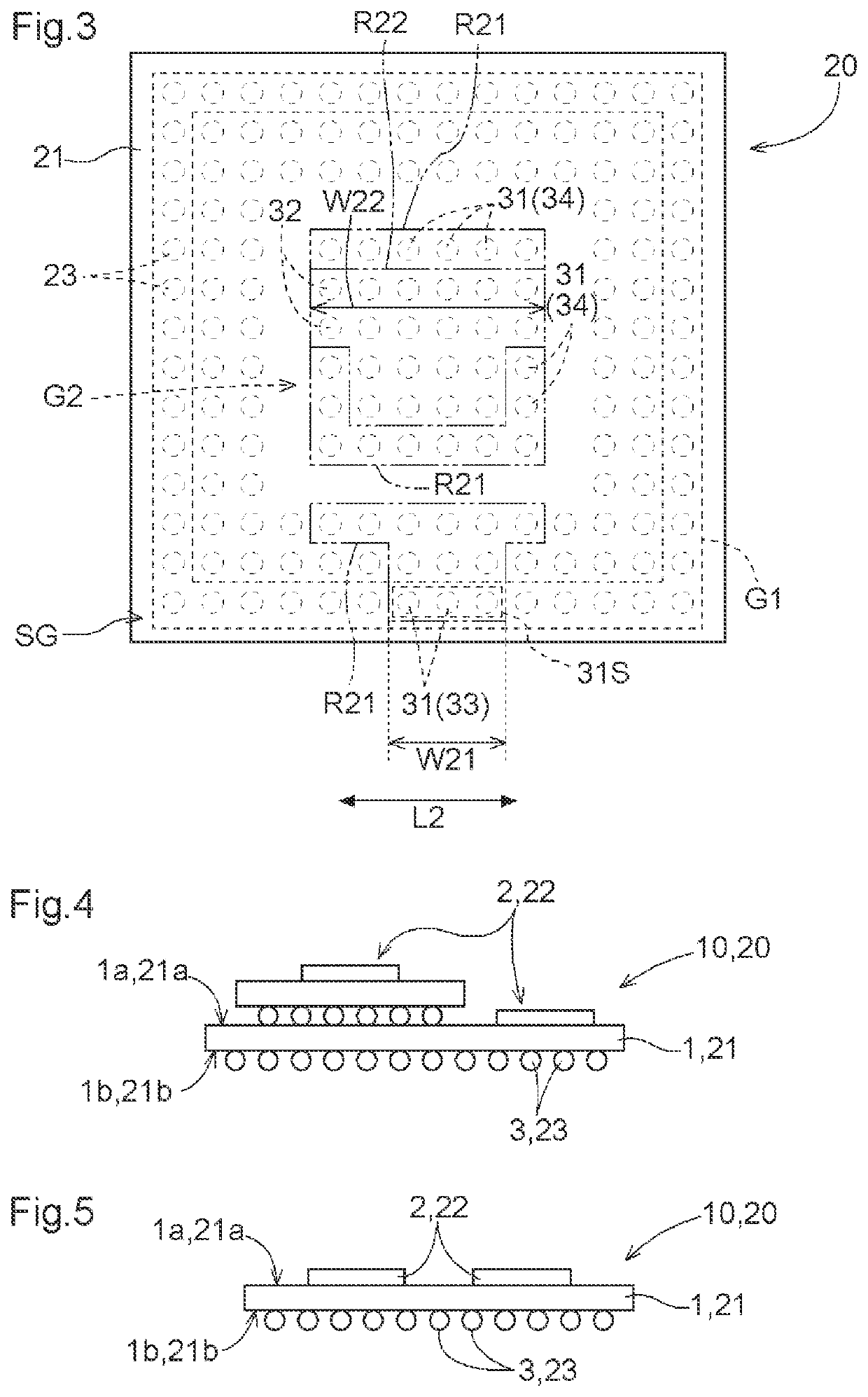
[0028]Hereinafter, an embodiment of a power supply chip module that is a power supply source, and a circuit module configured by including the power supply chip module and a load chip module that is a power supply destination of the power supply chip module will be described with reference to the drawings. As shown in FIG. 1, a circuit module 80 includes a power supply chip module 10, a load chip module 20, and a system board 30 serving as a mounting board that supports the power supply chip module 10 and the load chip module 20. The load chip module 20 is connected to the power supply chip module 10 and is supplied with power from the power supply chip module 10. FIG. 1 shows as an example, a form in which the power supply chip module 10 and the load chip module 20 are supported on a system board first surface 30a, and a first power supply wiring pattern 41 (first wiring pattern) is formed on the system board first surface 30a. As shown in FIG. 9, which is a cross-sectional view of...


PUM


Abstract

Provided is a circuit module including a power supply chip module, a load chip module, and a system board. A power supply output terminal group of the power supply chip module is arranged side by side in a row along a side of the power supply chip module board, the power supply input terminal group of a load chip module includes a specific terminal group arranged in a specific row that is a row along a side of the load chip module board, and a wiring width along an arrangement direction of the power supply output terminal group of a wiring pattern in which the power supply output terminal group is connected to the system board is equal to or more than a wiring width W31 along an arrangement direction of the specific terminal group of the wiring pattern in which the specific terminal group is connected to the system board.

Description

CROSS REFERENCE TO RELATED APPLICATIONS[0001]This Application is a National Stage of International Application No. PCT / JP2019 / 020914 filed May 27, 2019, which designates the United States, and which claims the benefit of priority from Japanese Patent Application No. 2018-130940 Filed Jul. 10, 2018, the entire contents of which are incorporated herein by reference.TECHNICAL FIELD[0002]The present disclosure relates to a circuit module including a power supply chip module, a load chip module, and a system board that supports the power supply chip module and the load chip module, and the power supply chip module.BACKGROUND ART[0003]Japanese Unexamined Patent Application Publication No. 2014-82245 (JP 2014-82245 A) discloses a semiconductor memory device having a controller (201) and a power supply IC (202) (numerals in parentheses in the BACKGROUND ART refer to those of the referenced document). The power supply IC (202) generates a plurality of different power supply voltages and supp...

Claims


Application Information

Patent Timeline
Patent Type & Authority Patents(United States)
IPC IPC(8): H01R9/00H01L23/498H01L25/18H05K1/02H05K1/11H05K1/18H01L25/10
CPCH01L23/49838H01L23/49816H01L25/18H05K1/0298H05K1/112H05K1/181H01L23/49833H01L25/105H05K2201/09227H05K2201/09409H05K2201/09609H05K2201/09672H05K2201/09727H05K2201/10522H05K2201/10545H01L23/12H01L2924/15311H01L2924/15192H01L2924/15331H01L2225/1023H01L2225/1058H01L2225/107H01L25/0655H01L2224/16227H01L2225/1011H01L23/5384H01L23/5386H05K1/0265H05K2201/093G06F1/188G06F1/20H05K2201/10734H05K2201/10674H05K1/111G06F1/189G06F1/183G06F1/26H01L23/525H01L23/528H01L23/50H01L25/04
Inventor KUSANO, TAKASHINARUSE, TAKANOBU
Owner AISIN CORP
Why Eureka
Try Eureka