Liquid ejecting head and liquid ejecting apparatus

a liquid ejecting head and liquid ejecting technology, applied in printing and other directions, can solve the problems of generating more heat and reducing the width and achieve the effect of reducing the size of the liquid ejecting head

Active Publication Date: 2018-09-20
SEIKO EPSON CORP
View PDF1 Cites 3 Cited by
  • Summary
  • Abstract
  • Description
  • Claims
  • Application Information

AI Technical Summary

Benefits of technology

[0005]An advantage of some aspects of the invention is that the size of a liquid ejecting head may be reduced while ensuring wiring width.
[0006]A liquid ejecting head according to an aspect of the invention includes a liquid ejection unit, a flexible substrate, and a case member. The liquid ejection unit includes a drive element, a pressure chamber, and a nozzle. A pressure of the pressure chamber is changed in accordance with drive of the drive element to eject a liquid from the nozzle. The flexible substrate is electrically connected to the drive element. The case member includes a flow channel configured to supply the liquid to the pressure chamber and an opening portion through which the flexible substrate is inserted. The flexible substrate has a straight portion and a wide portion having a width more than that of the straight portion. The case member has a side wall surrounding the opening portion, and a cutout portion formed in the side wall and configured to release the opening portion outward from the side wall. Portions of the side wall across the cutout portion are positioned outside the straight portion of the flexible substrate disposed in the opening portion. According to such a configuration, since the flexible substrate has the straight portion, and the wide portion having a width more than that of the straight portion, a wiring width can be sufficiently ensured to suppress heat generation. In addition, since the side wall surrounding the opening portion of the case member has a side wall formed with the cutout portion configured to release the opening portion outward from the side wall, and portions of the side wall across the cutout portion are positioned outside the straight portion of the flexible substrate disposed in the opening portion, the straight portion of the flexible substrate can be inserted into the opening portion from the cutout portion in the side wall to be stored in the opening portion. According to such a configuration, since the size of the opening portion does not need to be increased to insert the wide portion of the flexible substrate through the opening portion, the size of the opening portion can be reduced and thus the size of the liquid ejecting head can be reduced. Therefore, according to this aspect, the liquid ejecting head can be reduced in size while sufficiently ensuring a wiring width.
[0007]It is preferable that the portions of the side wall across the cutout portion form projecting portions projecting outside the straight portion of the flexible substrate disposed in the opening portion, and that a length from a bonding surface of the liquid ejection unit, on which the case member is bonded, to a boundary between the straight portion and the wide portion, be more than a height of the projecting portions from the bonding surface. According to such a configuration, since a length from the bonding surface of the liquid ejection unit, on which the case member is bonded, to the boundary between the straight portion and the wide portion, is more than a height of the projecting portions from the bonding surface, the flexible substrate can be inserted from the cutout portion into the opening portion such that the wide portion does not interfere with the projecting portions. Since the portions of the side wall across the cutout portion form projecting portions projecting outside the straight portion of the flexible substrate disposed in the opening portion, the projecting portions and the other parts of the side wall are readily held by hand, and even if the projecting portions and the side wall are held by hand, the flexible substrate is prevented from being touched by hand.

Problems solved by technology

When the width of the flexible substrate is, however, reduced, wiring width is also reduced, resulting in generating more heat.

Method used


Image

  • Liquid ejecting head and liquid ejecting apparatus
  • Liquid ejecting head and liquid ejecting apparatus
  • Liquid ejecting head and liquid ejecting apparatus

Examples


first embodiment

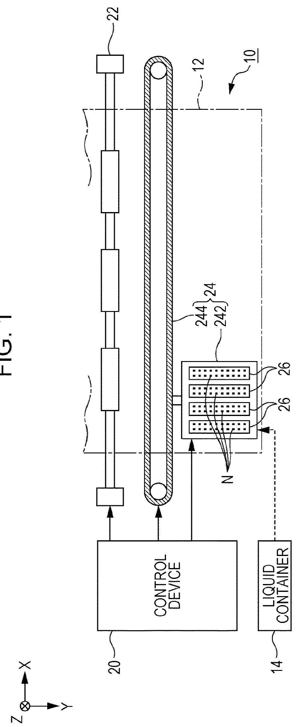
[0041]FIG. 1 is a schematic diagram illustrating an example of a liquid ejecting apparatus 10 according to a first embodiment of the invention. The liquid ejecting apparatus 10 according to the first embodiment is an ink jet printer that ejects a liquid, such as ink, onto a medium 12. The medium 12 is typically printing paper, but any object, such as a resin film or a fabric, may be used as the medium 12 for printing. As illustrated in FIG. 1, a liquid container 14 configured to store ink is fixed to the liquid ejecting apparatus 10. For example, a cartridge detachable from the liquid ejecting apparatus 10, an ink pack made of a flexible film in a bag shape, or an ink tank configured to be replenished with ink may be used as the liquid container 14. Different colors of ink may be stored in the liquid container 14.

[0042]As illustrated in FIG. 1, the liquid ejecting apparatus 10 includes a control device 20, a transport mechanism 22, a movement mechanism 24, and a plurality of liquid ...


PUM


Abstract

A liquid ejecting head includes a liquid ejection unit, a flexible substrate, and a case member. The liquid ejection unit includes a drive element, a pressure chamber, and a nozzle. The flexible substrate is electrically connected to the drive element. The case member includes a flow channel configured to supply the liquid to the pressure chamber and an opening portion through which the flexible substrate is inserted. The flexible substrate has a straight portion and a wide portion having a width more than that of the straight portion. The case member has a side wall surrounding the opening portion, and a cutout portion formed in the side wall and configured to release the opening portion outward from the side wall. Portions of the side wall across the cutout portion are positioned outside the straight portion of the flexible substrate disposed in the opening portion.

Description

[0001]The entire disclosure of Japanese Patent Application No. 2017-052102, filed Mar. 17, 2017 is expressly incorporated by reference herein.BACKGROUND1. Technical Field[0002]The present invention relates to a technique for ejecting a liquid such as ink.2. Related Art[0003]Liquid ejecting heads for ejecting liquid such as ink from a plurality of nozzles have been proposed. For example, JP-A-2011-167956 discloses a liquid ejecting head in which a liquid stored in a liquid storage chamber (a common liquid chamber) is supplied to a plurality of pressure chambers and the pressure in each pressure chamber is changed by drive elements such as piezoelectric elements to eject the liquid from nozzles. In the technique of JP-A-2011-167956, the liquid storage chamber is formed in a case member (a unit case), the case member is provided with an opening portion entirely and circumferentially surrounded by a side wall, and a flexible substrate (a flexible cable) is inserted through the opening p...

Claims


Application Information

Patent Timeline
Patent Type & Authority Applications(United States)
IPC IPC(8): B41J2/14
CPCB41J2/14233B41J2002/14241B41J2002/14266B41J2002/14491B41J2002/14419
Inventor TOMIMATSU, SHINGOWATANABE, SHUNSUKE
Owner SEIKO EPSON CORP
Why Eureka
Try Eureka