Applique with deployable aerodynamic surface

Active Publication Date: 2022-05-24
MAGNA EXTERIORS INC
View PDF18 Cites 0 Cited by
  • Summary
  • Abstract
  • Description
  • Claims
  • Application Information

AI Technical Summary

Benefits of technology

The present invention provides an aerodynamic member for a vehicle that can remain in a stowed position during slow vehicle speeds and selectively move to a deployed position at increased speeds to improve fuel economy. The aerodynamic member does not increase or significantly increase head-on drag of the vehicle and minimizes drag while moving from the stowed position to the deployed position at highway speeds. It remains generally flush with an outer body panel of the vehicle.

Problems solved by technology

However, in certain types of vehicles, particularly larger vehicles, such as vans, sport utility vehicles, and the like, providing aerodynamic contours and features can prove difficult.
Although some advances have been made in contouring the fixed shape of vehicle panels for these types of vehicles, and others, the drag created at the rear of vehicles, known as base drag, remains a problem.
Turbulent air flow results from air suddenly separating in uncontrolled fashion from the rear of the vehicle.
Turbulent air flow results in a negative pressure (vacuum) at the rear of the vehicle, which in turns results in the base drag force acting as a pulling force on the rear of the vehicle, which in turn ultimately reduces the fuel economy of the vehicle.
Spoilers, fins and the like, which protrude outwardly from the surface of vehicles have been met with some success, but they inherently result in increased drag as a result of increasing the vehicle surface area exposed to head-on airflow.
In addition, spoilers, fins and the like can prove unsightly.

Method used


Image

  • Applique with deployable aerodynamic surface
  • Applique with deployable aerodynamic surface
  • Applique with deployable aerodynamic surface

Examples


Embodiment Construction

[0035]The following description of the preferred embodiment is merely exemplary in nature and is in no way intended to limit the invention, its application, or uses.

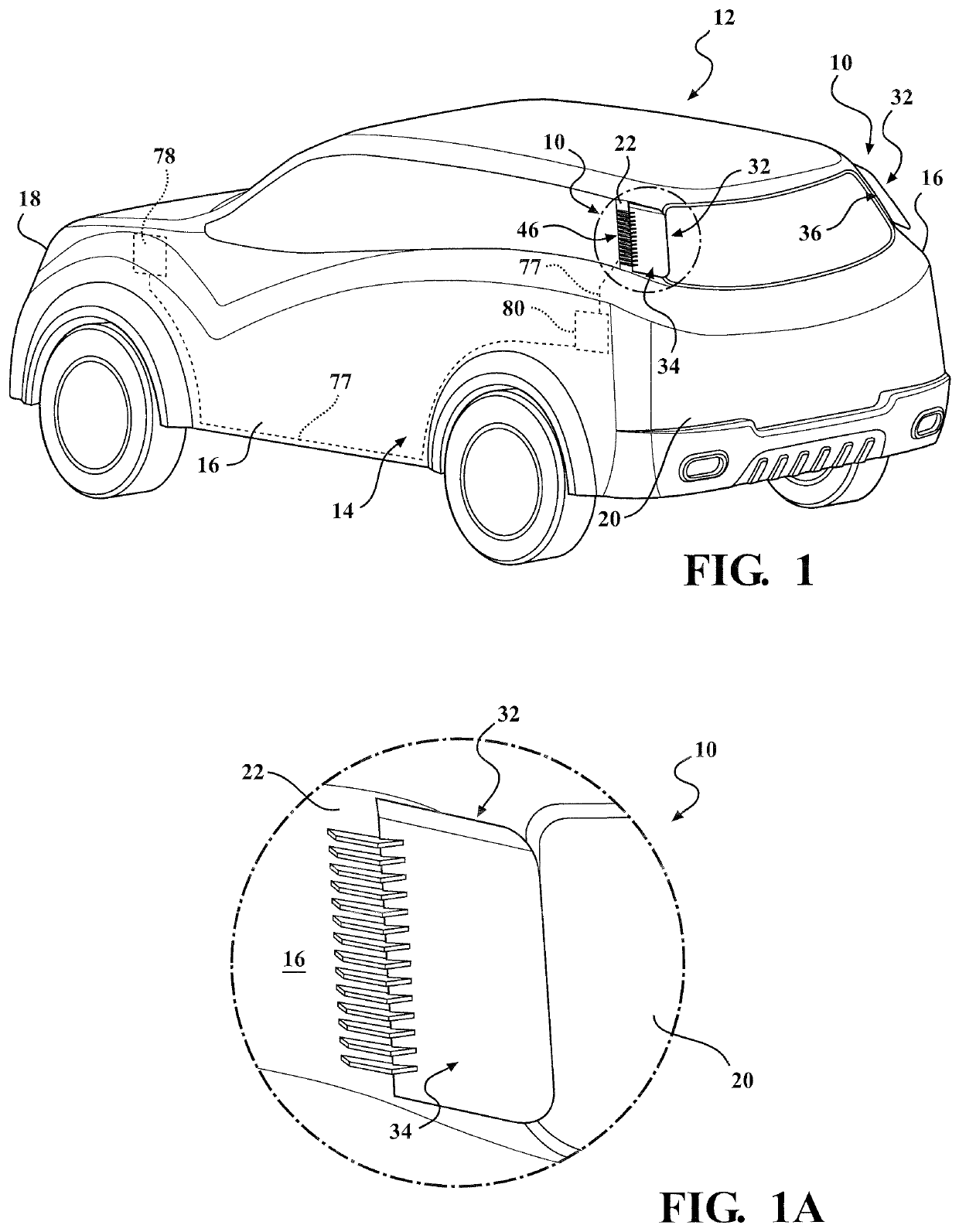
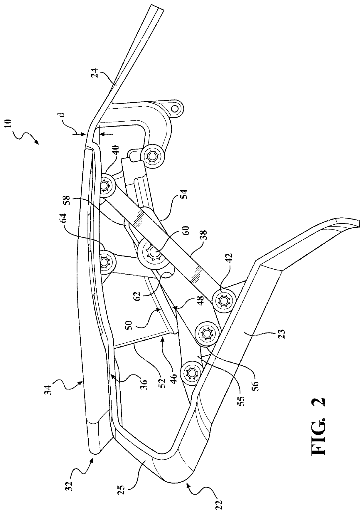
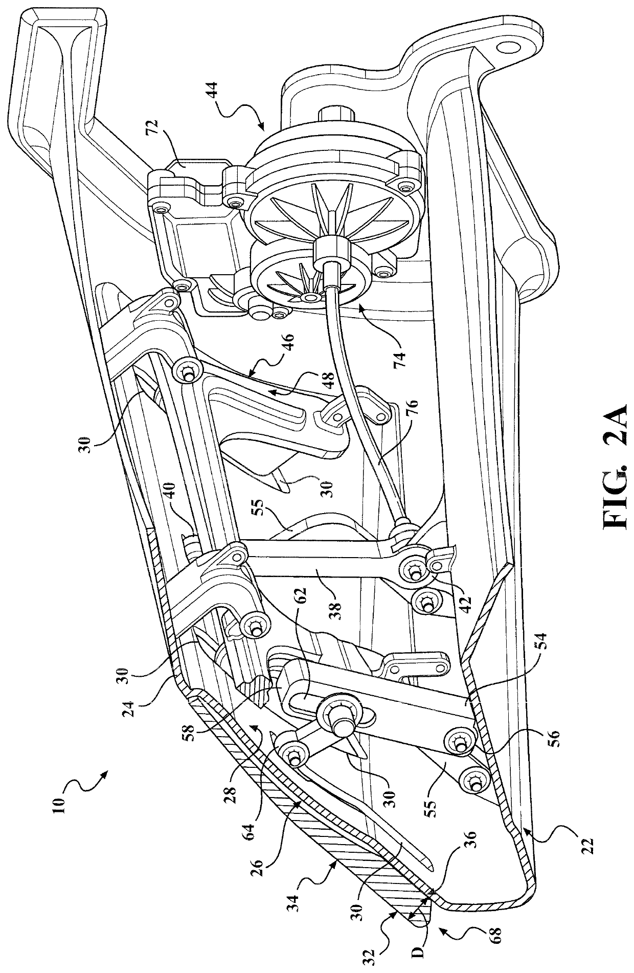
[0036]In general, example embodiments of an assembly 10, which is an actively deployable vehicle applique assembly having a deployable aerodynamic panel, also referred to as surface, constructed in accordance with the teachings of the present disclosure will now be disclosed. The example embodiments are provided so that this disclosure will be thorough, and will fully convey the scope to those who are skilled in the art. Numerous specific details are set forth such as examples of specific components, devices, and methods, to provide a thorough understanding of embodiments of the present disclosure. It will be apparent to those skilled in the art that specific details need not be employed, that example embodiments may be embodied in many different forms and that neither should be construed to limit the scope of the disclo...


PUM


Abstract

A deployable applique assembly for a motor vehicle is provided. The assembly includes a housing having a wall with at least one through opening extending through the wall and a panel configured to overlie at least a portion of the wall when in a stowed position, with an outer surface of the panel being configured to form a smooth surface with a body panel of the motor vehicle. The assembly includes a drive link extending through the at least one through opening and having a first end operatively coupled to the inner surface of the panel and a second end. An actuator has a drive member operably coupled with the second end of the drive link, wherein the actuator is operable to selectively pivot the drive link to move the panel between the stowed position and a deployed position.

Description

CROSS-REFERENCE TO RELATED APPLICATIONS[0001]This application claims the benefit of U.S. Provisional Application No. 62 / 610,600, filed Dec. 27, 2017. The disclosure of the above application is incorporated herein by reference.FIELD OF THE INVENTION[0002]The present disclosure relates generally to aerodynamic devices for vehicles, and more particularly, to aerodynamic devices for vehicles that are moveable between stowed and deployed positions.BACKGROUND OF THE INVENTION[0003]This section provides background information related to the present disclosure which is not necessarily prior art.[0004]Vehicles are continually being designed to attain improved fuel economy, particularly in view of ever increasing fuel prices and emissions standards. In an effort to improve fuel economy, the shape of a vehicle is generally taken into consideration to improve its aerodynamics, particularly at highway speeds. It is known that the aerodynamics of vehicle play an important role in increasing fuel ...

Claims


Application Information

Patent Timeline
IPC IPC(8): B62D35/00
CPCB62D35/007B62D37/02B62D35/008Y02T10/82
Inventor FERRI, JAMES J.MITCHELL, J. R. SCOTTDOMENCHINI, JEFFREY RICHARD F.
Owner MAGNA EXTERIORS INC
Why Eureka
Try Eureka