

Flight control surface assembly
a control surface and assembly technology, applied in aircraft power plants, power amplification, transportation and packaging, etc., can solve the problems of relatively high complexity and/or weight, and relatively low efficiency, and achieve the effect of simple and cost-efficient arrangemen
- Summary
- Abstract
- Description
- Claims
- Application Information
AI Technical Summary
Benefits of technology
Problems solved by technology
Method used
Image

Examples
Embodiment Construction
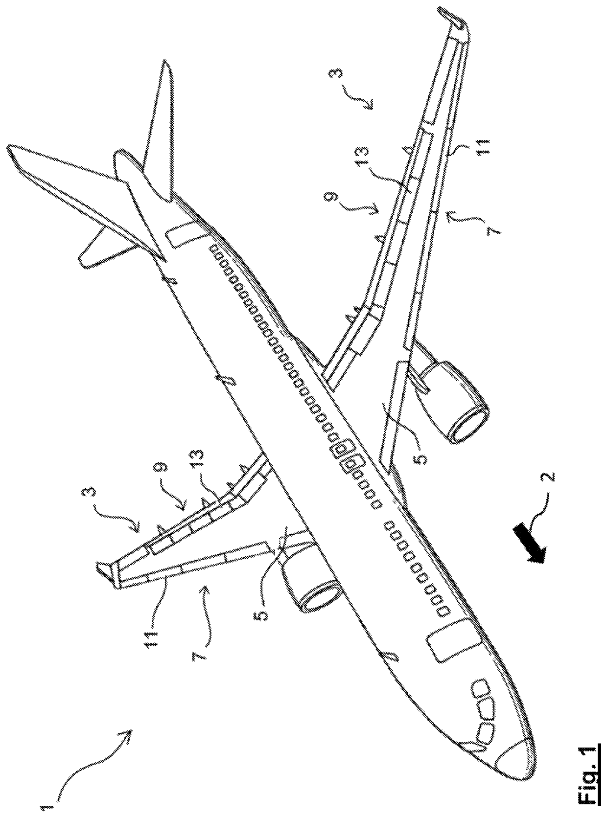
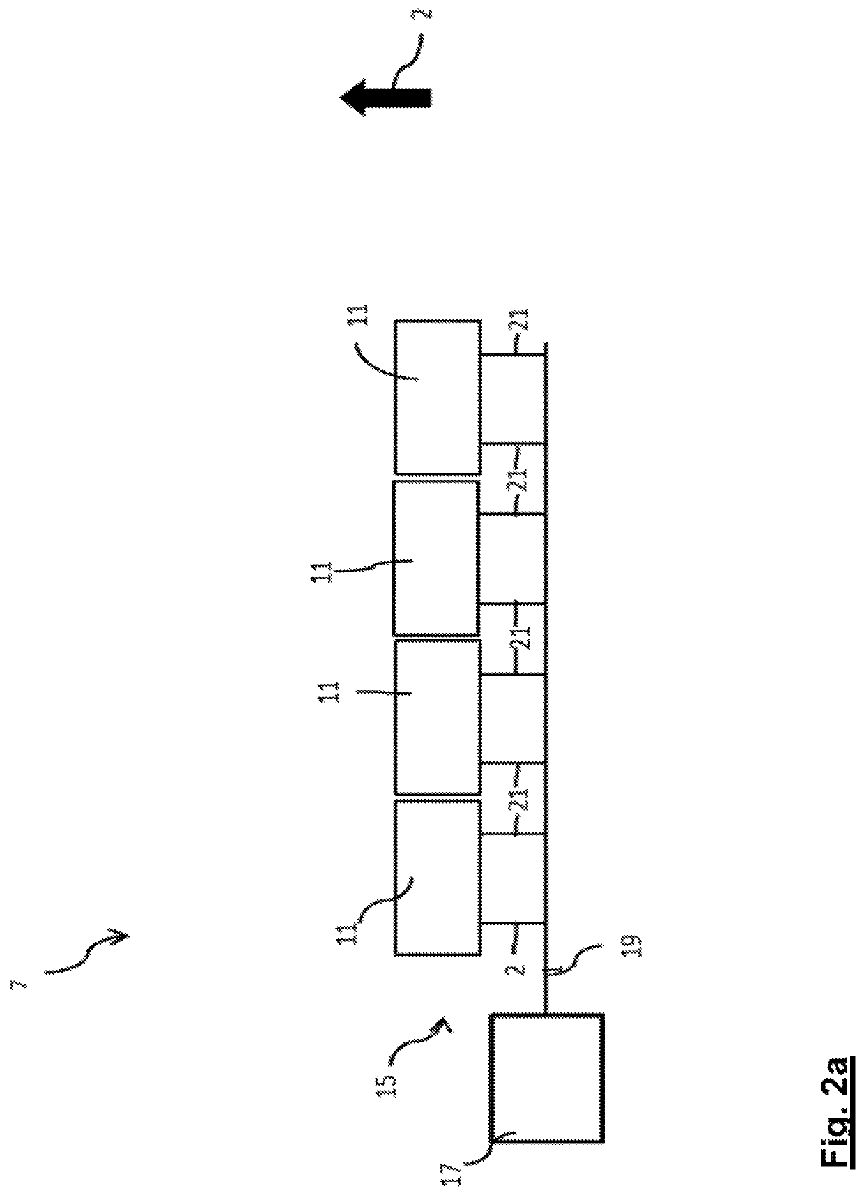
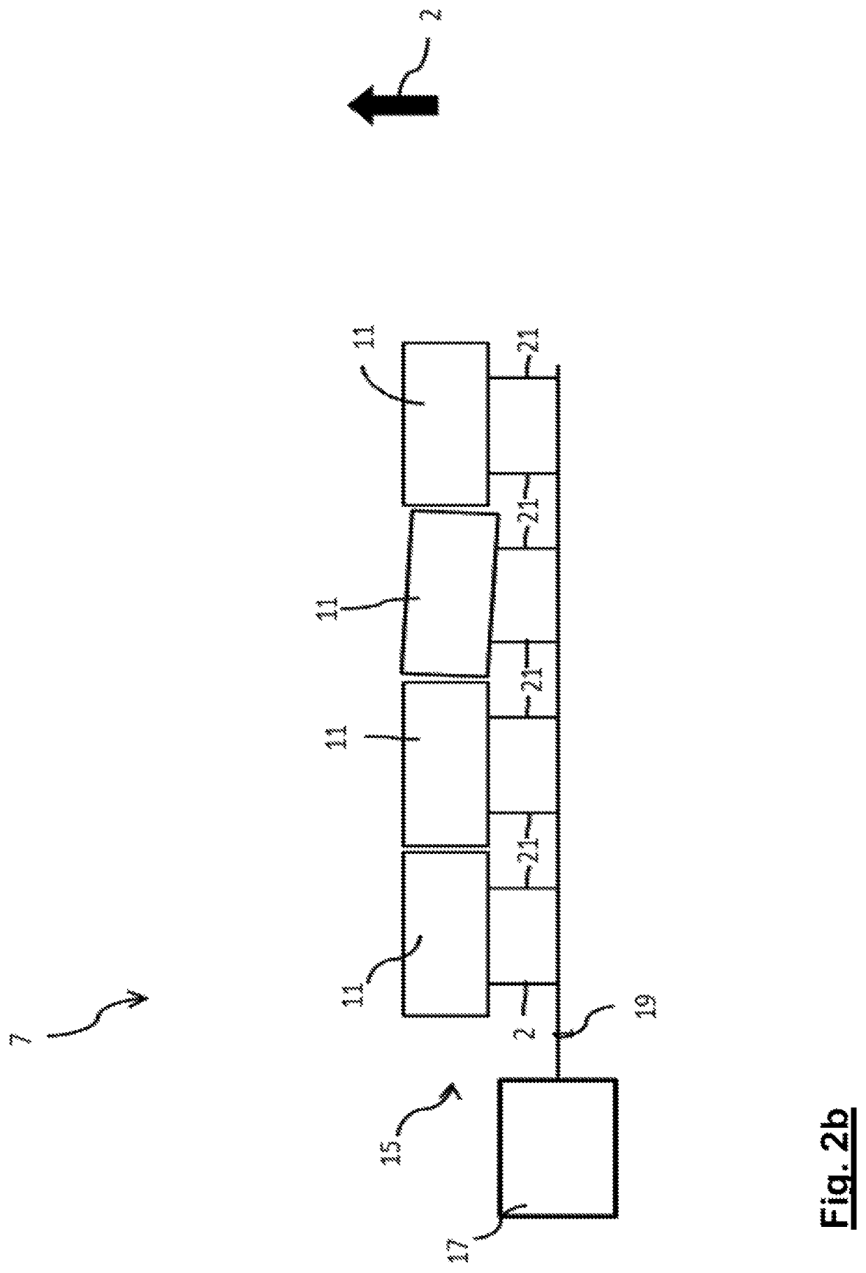
[0033]In FIG. 1 an aircraft 1 comprising two wings 3 is shown. Each of the wings 3 comprises a main wing 5 and two flight control surface assemblies, namely a leading edge flight control surface assembly in the form of a slat assembly 7, and a trailing edge flight control surface assembly in the form of a flap assembly 9. Each of the slat assemblies 7 comprises four flight control surfaces in the form of slats 11, which are arranged side by side in a row, and each of the flap assemblies 9 comprises four flight control surfaces in the form of flaps 13, which are likewise arranged side by side in a row. In FIG. 1 the slats 11 and flaps 13 are shown in a retracted or stowed position in which the leading edges of the slats 11 are essentially aligned with the leading edges of the main wings 5 and the trailing edges of the flaps 13 are essentially aligned with the trailing edges of the main wings 5. The arrow 2 indicates the flight direction, i.e. when moving the slats 11 into the extende...
PUM
 Abstract
Description
Claims
Application Information