Flight Control Surface Assembly

a control surface and assembly technology, applied in the direction of movable aircraft element position indicators, power amplification, aircraft power plants, etc., can solve the problems of relatively high complexity and/or weight, and relatively low efficiency, and achieve the effect of simple and cost-efficient arrangemen

Active Publication Date: 2019-11-28
AIRBUS OPERATIONS GMBH
View PDF0 Cites 0 Cited by
  • Summary
  • Abstract
  • Description
  • Claims
  • Application Information

AI Technical Summary

Benefits of technology

[0007]Aspects of the present invention may provide a flight control surface assembly of the above type, which is of a simple and cost-efficient construction and which is nevertheless able to address a fault state in which one of the flight control surfaces deviates considerably from its predetermined nominal path.
[0017]This configuration is very simple and can be configured to not being influenced by wing bending, i.e. the risk of false alarms caused by wing bending can be reduced. For example, skewing of a flight control surface, such as a slat, can be reliably detected. As compared to mechanical solutions for preventing excessive deviations from the predetermined synchronous movement and, in particular, skewing of a flight control surface or slat, the weight of the assembly is considerably reduced. The assembly also has the advantage that it is very simple to produce and to install and to maintain. For example, a flight control surface can be easily removed and install, because it is merely necessary to disconnect and to connect, respectively, the transmission mechanism from and to the flight control surface, e.g. the first and second wire-shaped elements mentioned below. Further, the detection signals of all of the flight control surfaces can be fed to a single detection or control unit, which evaluates the detection signals and takes appropriate steps.
[0019]In a preferred embodiment, for each of the at least one flight control surface one or more or all of the one or more projecting elements are integrally formed in one piece with the second axial end face or another portion of the second roller. Alternatively, or in combination with this embodiment, one or more or all of the one or more projecting elements are an element which is separate from the second roller and is retained in the fixed position on the second axial end face. In the latter case, each of the projecting elements, which is an element separate from the second roller, is preferably a ball rotatably held in an associated recess in the second axial end face. Configuring the projecting elements in this manner as a ball provides the advantage that the projecting elements can roll on the cam surface portion, so that friction and wear between the projecting elements and the cam surface portion are reduced.
[0021]In a preferred embodiment, the transmission mechanism of each of the one or more flight control surfaces comprises a first and a second wire-shaped element, each coupled mechanically at one end thereof to the associated flight control surface to move under mechanical tension along their length together with the flight control surface upon movement thereof between the retracted and extended positions. The coupling is such that the movement of the first wire-shaped element along its length corresponds to—i.e. is related to, is a function of or is synchronized with—the movement of the first portion of the flight control surface and the movement of the second wire-shaped element along its length corresponds to—i.e. is related to, is a function of or is synchronized with—the movement of the second portion of the flight control surface. The first and second wire-shaped elements may be coupled directly or indirectly to the flight control surface, e.g. directly to the flight control surface, indirectly via separate components which are in turn connected to the flight control surface, or to a drive component, such as an actuator, adapted to drive the predetermined movement of the flight control surface. In particular, the first and second wire-shaped elements may be coupled directly to the first portion and the second portion, respectively, such as to two tracks, e.g. slat tracks in the case of slats, or to two portions of the main body of the flight control surface. Generally, the first and second wire-shaped elements are elongate flexible elements, such as wires, cables or belts, and have an arbitrary cross-section, but preferably a circular cross-section. The first wire-shaped element is guided at least partially around the first roller and the second wire-shaped element is guided at least partially around the second roller to effect the rotation of the first and second rollers. The rotation of the rollers is effected due to a torque applied by the wire-shaped elements when they move together with the flight control surface. The synchronous rotation of the first and second rollers when the flight control surface carries out the predetermined movement may be set in a simple manner by, e.g., choosing suitable diameters of the first and second rollers. This embodiment provides the advantage that due to the use of the wire-shaped elements it is particularly simple to reduce or avoid an influence of wing bending on the detection.
[0023]In the above embodiments, in which the transmission mechanism of each of the one or more flight control surfaces comprises a first and a second wire-shaped element, it is further preferred if the transmission mechanism of each of the at least one flight control surface further comprises a first deflection pulley and a second deflection pulley. The first deflection pulley is arranged, along the length of the first wire-shaped element, between the flight control surface and the first roller such that the first wire-shaped element is guided at least partially around the first deflection pulley and extends between the flight control surface and the first deflection pulley in a chord direction of the flight control surface. Similarly, the second deflection pulley is arranged, along the length of the second wire-shaped element, between the flight control surface and the second roller such that the second wire-shaped element is guided at least partially around the second deflection pulley and extends between the flight control surface and the second deflection pulley in a chord direction of the flight control surface. This provides the advantage, that when the flight control surface is mounted to a wing of an aircraft, the first and second wire-shaped elements extend from the flight control surface in the flight direction or chord direction of the wing, and that the first and second deflection pulleys can be arranged such that the first and second wire-shaped elements extend along the neutral axis of the wing between the first and second deflection pulleys and the first and second rollers, so that the influence of wing bending on the detection is reduced or even eliminated altogether in a very simple and reliable manner. Therefore, the triggering tolerances can be set to a low value and the risk of false alarms is reduced.

Problems solved by technology

However, this approach is associated with relatively high costs and with a relatively high complexity and / or weight.
The aircraft is able to safely fly, irrespective of the position of the flight control surfaces, albeit with a somewhat decreased efficiency.
However, the arrangement of spherical bearings used in the joints, typically together with multiple links, is relatively complex and expensive and assumes a considerable amount of space.

Method used


Image

  • Flight Control Surface Assembly
  • Flight Control Surface Assembly
  • Flight Control Surface Assembly

Examples


Embodiment Construction

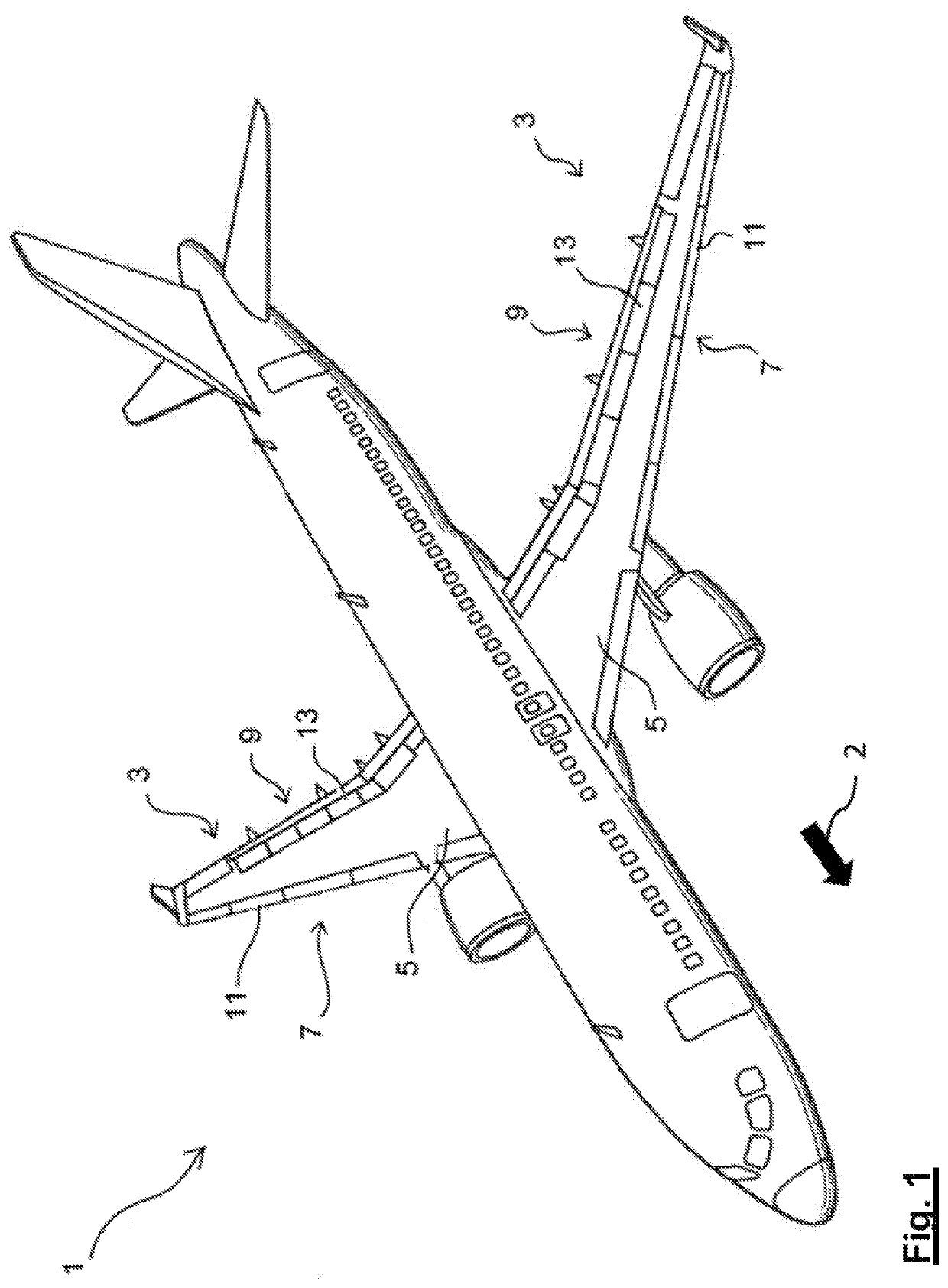
[0033]In FIG. 1 an aircraft 1 comprising two wings 3 is shown. Each of the wings 3 comprises a main wing 5 and two flight control surface assemblies, namely a leading edge flight control surface assembly in the form of a slat assembly 7, and a trailing edge flight control surface assembly in the form of a flap assembly 9. Each of the slat assemblies 7 comprises four slats 11, which are arranged side by side in a row, and each of the flap assemblies 9 comprises four flaps 13, which are likewise arranged side by side in a row. In FIG. 1 the slats 11 and flaps 13 are shown in a retracted or stowed position in which the leading edges of the slats 11 are essentially aligned with the leading edges of the main wings 5 and the trailing edges of the flaps 13 are essentially aligned with the trailing edges of the main wings 5. The arrow 2 indicates the flight direction, i.e. when moving the slats 11 into the extended position they are moved with respect to the main wing 5 in the flight direct...


PUM


Abstract

A flight control surface assembly adapted to be mounted to a main wing of an aircraft includes a flight control surface having a first portion and a second portion spaced from each other, a connection assembly adapted for movably connecting the flight control surface to the main wing, such that the flight control surface is selectively movable in a predetermined movement between a retracted position and an extended position with respect to the main wing, and for each of the flight control surface, a first roller with a first axial face and a second roller with a second axial face facing the first axial face mounted rotatably and coaxially. with a gap between the first and second axial end faces. A biasing mechanism biasing the first and second rollers towards each other, and a transmission mechanism coupled between the flight control surface and the rollers are included.

Description

FIELD OF THE INVENTION[0001]The present application relates to a flight control surface assembly, such as a leading edge slat assembly.[0002]An embodiment of the leading edge slat assembly comprises one or more flight control surface having a first portion and a second portion spaced from each other, a connection assembly adapted for movably connecting the one or more flight control surfaces to a main wing of an aircraft, such that each of the flight control surfaces is selectively movable in a predetermined movement between a retracted position and an extended position with respect to the main wing.BACKGROUND OF THE INVENTION[0003]In order to be able to selectively vary the degree of lift provided by an aircraft wing, aircraft wings are typically provided with aerodynamic or flight control surfaces which are movably coupled to a main wing such that they can be moved between a retracted or stowed position, in which they are disposed within or directly on the main wing, and at least ...

Claims


Application Information

Patent Timeline
Patent Type & Authority Applications(United States)
IPC IPC(8): B64C9/06B64C9/02B64C3/58
CPCB64C3/58B64C9/06B64C9/02B64C9/26B64C13/38B64D2045/001B64D45/0005B64C9/20
Inventor BENSMANN, STEFAN
Owner AIRBUS OPERATIONS GMBH
Why Eureka
Try Eureka