
Dry film formulation

a technology of dry film and adhesive, applied in the field of improved photoresist dry film layers, can solve the problems of inability to achieve suitable adhesion of the fluid flow layer to the silicon substrate, loss of significant adhesion enhancer, poor adhesion between the fluid flow layer and the substrate, etc., and achieve the effect of improving adhesion

Active Publication Date: 2022-05-24
FUNAI ELECTRIC CO LTD
View PDF6 Cites 0 Cited by
  • Summary
  • Abstract
  • Description
  • Claims
  • Application Information

AI Technical Summary

Benefits of technology

[0002]Photoresist dry film layers are useful for a wide variety of electronic devices, including but not limited to, fluid jet ejection devices, vaporization devices, and micro-electronic structures. Fluid jet ejection devices include fluidic ejection heads that are useful for ejecting a variety of fluids including inks, cooling fluids, pharmaceuticals, lubricants, vaporizing fluids, and the like. Devices that use fluidic ejection heads continue to be improved as the technology for making the fluidic ejection heads continues to advance. New techniques are constantly being developed to provide low cost, highly reliable fluidic ejection heads for fluid ejection devices for a wide variety of applications.
[0003]Fluidic ejection heads used in fluid jet ejection devices have a relatively complicated structure that includes electrical circuits, fluid passageways and a variety of tiny parts assembled with precision to provide a powerful, yet versatile fluidic ejection head. The components of the fluidic ejection head must cooperate with each other and with a variety of fluid formulations to provide the desired characteristics for ejecting fluid therefrom. Accordingly, it is important to match the ejection head components to the fluid and the duty cycle demanded by the fluid ejection device using the fluidic ejection head. Slight variations in production quality can have a tremendous influence on the product yield and resulting fluid ejection performance.
[0005]Due to the different chemical and physical properties of the silicon substrate and fluid flow layer, suitable adhesion of the fluid flow layer to the silicon substrate cannot be achieved without the use of surface treatment of the silicon substrate and / or the use of an adhesion enhancer in the fluid flow layer. Likewise, adhesion between the nozzle plate and the fluid flow layer is important and requires the use of an adhesion enhancer in the formulation for the dry film photoresist material used to make the nozzle plate layer. However, it was discovered that a considerable amount of adhesion enhancer is lost during the step of drying photoresist formulations on the release film. Loss of the adhesion enhancer during the drying step has led to poorer adhesion between the fluid flow layer and the substrate and / or between the fluid flow layer and the nozzle plate layer. Accordingly, what is needed is an improved dry film photoresist formulation that does not suffer from significant loss of the adhesion enhancer during the photoresist formulation drying step.
[0016]An advantage of the embodiments described herein is that the dry film photoimageable layer has improved adhesion between the semiconductor substrate and fluid flow layer and between the fluid flow layer and the nozzle plate compared to dry film photoimageable layers made with conventional adhesion enhancers.BRIEF DESCRIPTION OF THE DRAWINGS

Problems solved by technology

Fluidic ejection heads used in fluid jet ejection devices have a relatively complicated structure that includes electrical circuits, fluid passageways and a variety of tiny parts assembled with precision to provide a powerful, yet versatile fluidic ejection head.
Due to the different chemical and physical properties of the silicon substrate and fluid flow layer, suitable adhesion of the fluid flow layer to the silicon substrate cannot be achieved without the use of surface treatment of the silicon substrate and / or the use of an adhesion enhancer in the fluid flow layer.
However, it was discovered that a considerable amount of adhesion enhancer is lost during the step of drying photoresist formulations on the release film.
Loss of the adhesion enhancer during the drying step has led to poorer adhesion between the fluid flow layer and the substrate and / or between the fluid flow layer and the nozzle plate layer.

Method used


Image

  • Dry film formulation
  • Dry film formulation
  • Dry film formulation

Examples


Embodiment Construction

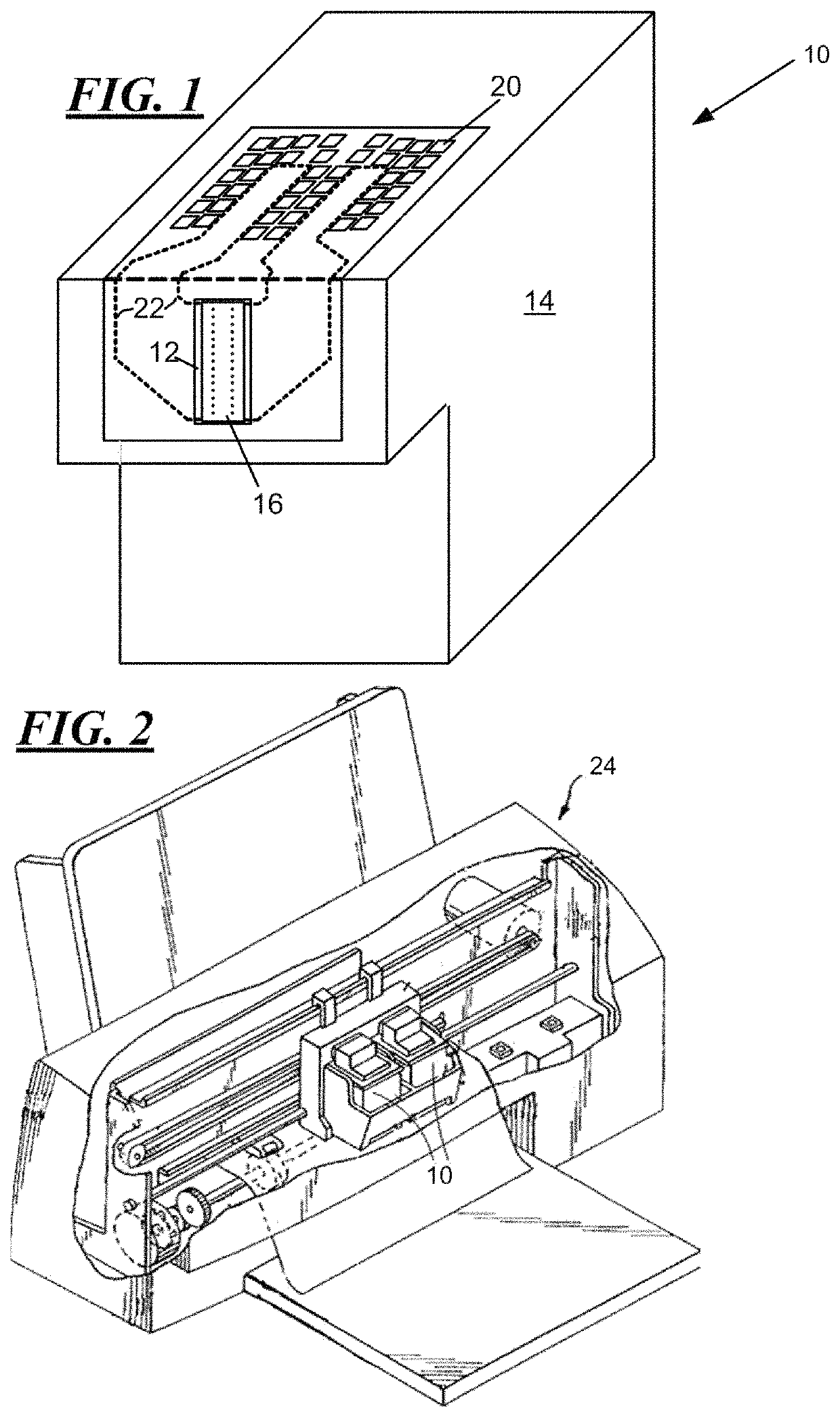
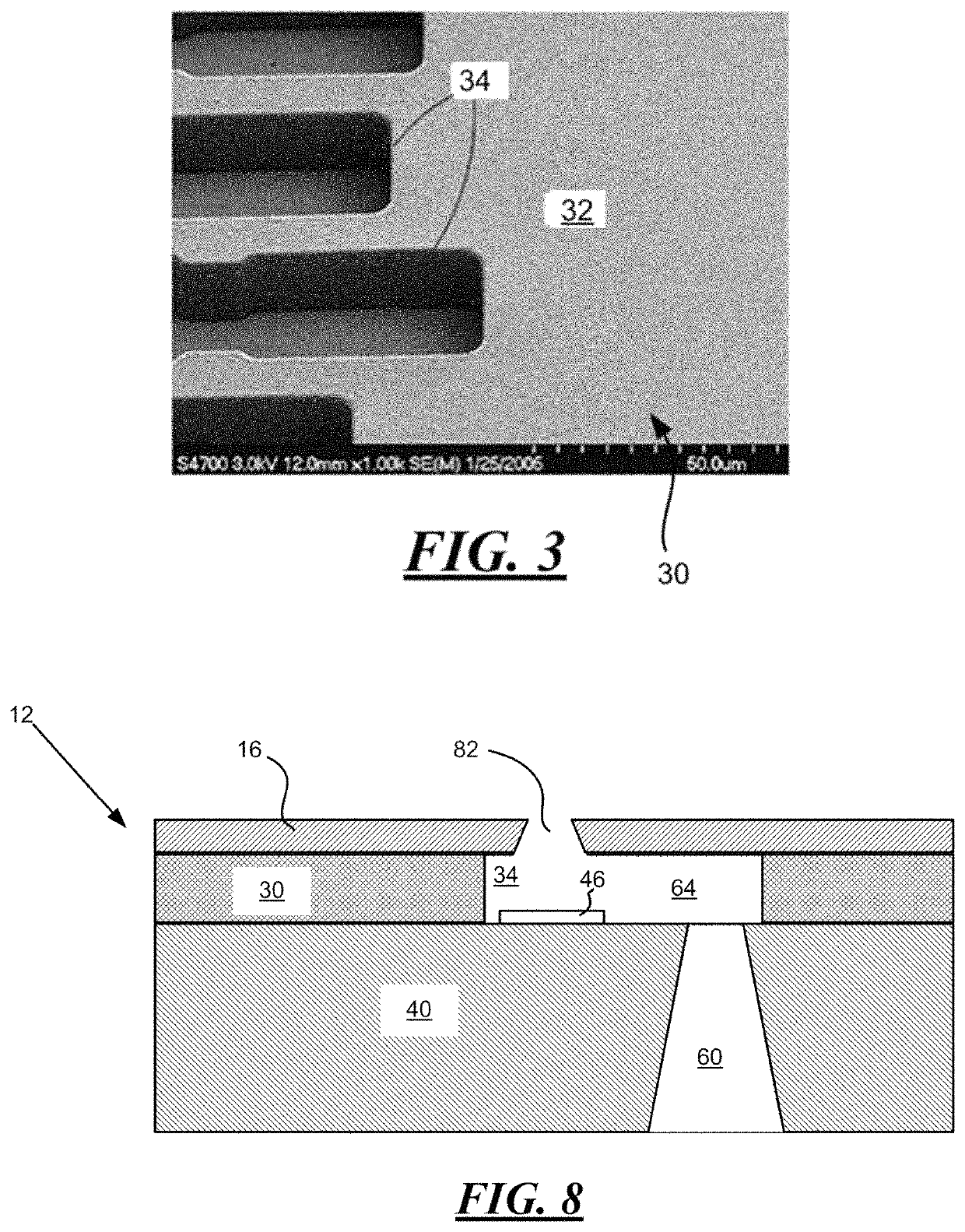
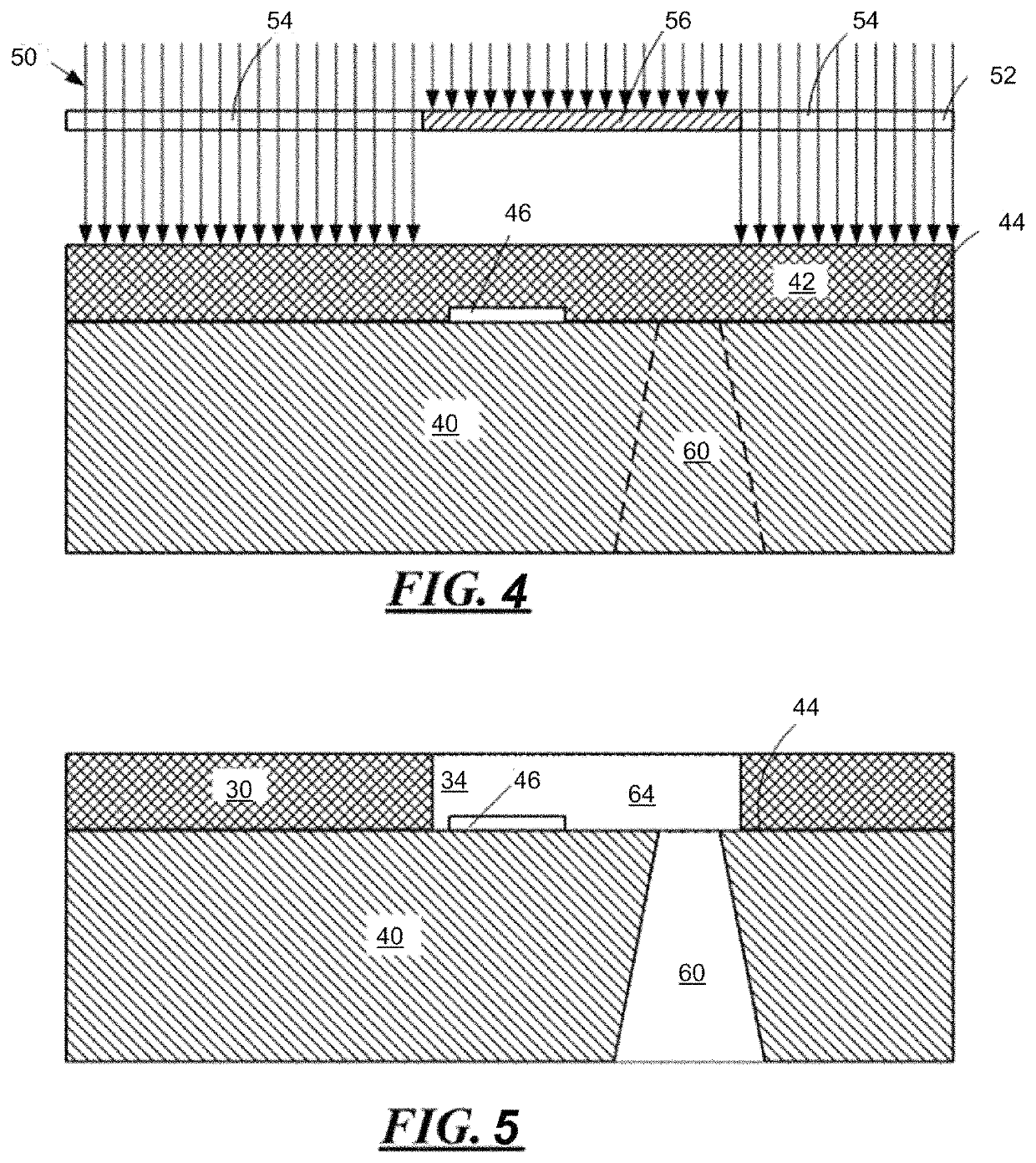
[0025]As set forth above, embodiments of the disclosure relate to improved photoimageable dry film formulations for fluidic ejection heads. A representative fluid ejection cartridge 10 containing a fluidic ejection head 12 is illustrated in FIG. 1. The fluid ejection cartridge 10 includes a cartridge body 14 for containing the fluidic ejection head 12 thereon. As described in more detail below, the ejection head 12 includes a nozzle plate 16 that is attached to the fluid flow layer, which in turn is attached to the silicon substrate containing fluid ejectors thereon. In a prior art fluidic ejection head, a nozzle plate made of a polyimide material is laser ablated and then attached by means of an adhesive to the fluid flow layer on the substrate. Such prior art process requires separate processing steps for the nozzle plate and difficult alignment techniques that are avoided by the use of the photoimageable dry film formulations described herein.

[0026]A flexible circuit 18 containin...


PUM

PropertyMeasurementUnit
temperatureaaaaaaaaaa
weight average molecular weightaaaaaaaaaa

Abstract

An improved photoimageable dry film formulation, a fluidic ejection head containing a thick film layer derived from the improved photoimageable dry film formulation, and a method for making a fluidic ejection head. The improved photoimageable dry film formulation includes a multifunctional epoxy compound, a photoinitiator capable of generating a cation, a non-photoreactive solvent, and from about 0.5 to about 5% by weight a silane oligomer adhesion enhancer based on a total weight of the photoimageable dry film formulation before drying.

Description

TECHNICAL FIELD[0001]The disclosure relates to improved photoresist dry film layers and in particular to photoresist dry film layers having improved formulations for making thick film laminates.BACKGROUND AND SUMMARY[0002]Photoresist dry film layers are useful for a wide variety of electronic devices, including but not limited to, fluid jet ejection devices, vaporization devices, and micro-electronic structures. Fluid jet ejection devices include fluidic ejection heads that are useful for ejecting a variety of fluids including inks, cooling fluids, pharmaceuticals, lubricants, vaporizing fluids, and the like. Devices that use fluidic ejection heads continue to be improved as the technology for making the fluidic ejection heads continues to advance. New techniques are constantly being developed to provide low cost, highly reliable fluidic ejection heads for fluid ejection devices for a wide variety of applications.[0003]Fluidic ejection heads used in fluid jet ejection devices have a...

Claims


Application Information

Patent Timeline
Patent Type & Authority Patents(United States)
IPC IPC(8): G03F7/075G03F7/30B41J2/14G03F7/004G03F7/038
CPCG03F7/0751B41J2/14233G03F7/0048G03F7/038G03F7/0752G03F7/30B41J2002/1425G03F7/0755G03F7/004B41J2/14B41J2/16C08G59/3281C08G59/4064C08G59/4071C09D163/00B41J2/1603B41J2/1631B41J2/1635B41J2/1634B41J2/1639
Inventor WEAVER, SEAN T.
Owner FUNAI ELECTRIC CO LTD
Learn More