
Methods and system operating a vehicle driveline

a technology for driving lines and vehicles, applied in the direction of gas pressure propulsion mounting, propulsion parts, transportation and packaging, etc., can solve the problem of reducing the number of times of approach, and achieve the effect of reducing engine emissions

Active Publication Date: 2022-05-31
FORD GLOBAL TECH LLC
View PDF14 Cites 0 Cited by
  • Summary
  • Abstract
  • Description
  • Claims
  • Application Information

AI Technical Summary

Benefits of technology

[0002]An engine may be included in a vehicle driveline that also includes an electrical machine. The engine may be started when the electrical machine lacks capacity to provide a desired driver demand power or during conditions when battery charge is low. If the engine and the engine's exhaust system are cold when the engine is started, engine emissions may be higher than is desired for a period of time. The engine may expel higher levels of hydrocarbons and carbon monoxide when the engine is cold due to hydrocarbons that may exit the engine without having participated in combustion. For example, hydrocarbons may become lodged between pistons and cylinder walls during compression and power strokes, but these hydrocarbons may be ejected from the engine's cylinders during exhaust strokes. The concentration of hydrocarbons ejected from an engine may be a function of many factors including engine load and engine temperature. If the engine's exhaust system is cold, higher concentrations of hydrocarbons and carbon monoxide may flow to atmosphere. Therefore, it may be desirable to provide a way of reducing engine emissions when an engine is cold started.
[0004]By decreasing an amount of power supplied to high voltage accessories that are coupled to a high voltage bus, it may be possible to provide the technical result of reducing engine loads after an engine start so that engine emissions may be reduced. In particular, an amount of power that is supplied to high voltage accessories may be reduced so that additional power may flow to an electric machine that provides propulsive force to the vehicle. Since power output of the electric machine may be increased, power output from the engine may be decreased while meeting driver demand power. Consequently, the engine may be operated at a lower load to reduce engine emissions until the engine is warm or until an even higher driver demand power is requested.
[0005]The present description may provide several advantages. For example, the approach may reduce engine emissions after engine starting. Further, the approach may reduce catalyst light-off times when a driver is requesting higher power demands. Further still, the approach may reduce a number of occasions when an engine is started to meet driver demand power.

Problems solved by technology

Further still, the approach may reduce a number of occasions when an engine is started to meet driver demand power.

Method used


Image

  • Methods and system operating a vehicle driveline
  • Methods and system operating a vehicle driveline
  • Methods and system operating a vehicle driveline

Examples


Embodiment Construction

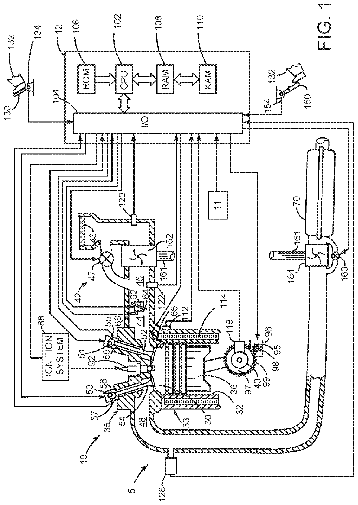
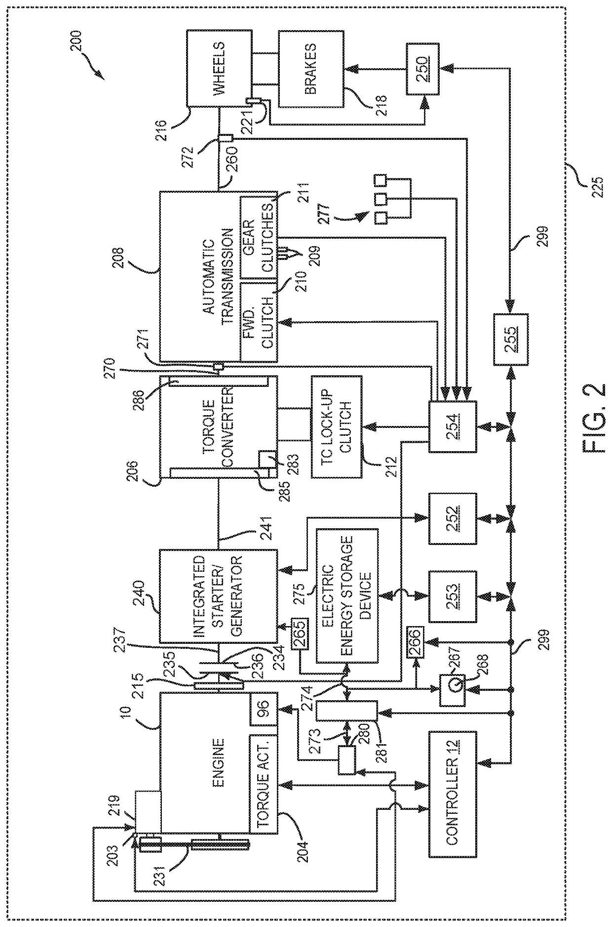
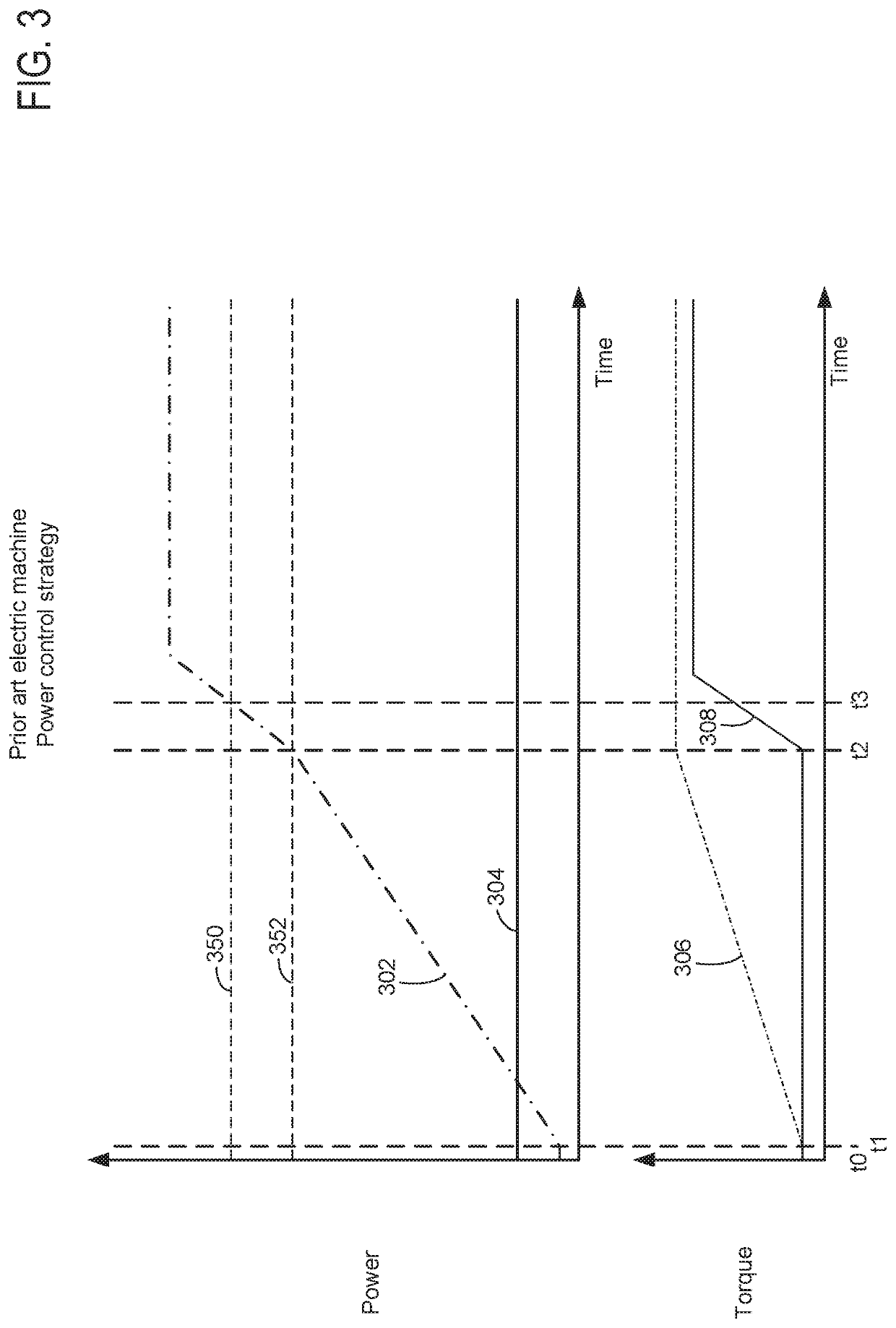
[0018]The present description is related to operating a driveline of a hybrid vehicle that includes an internal combustion engine and an electric machine. Power of a high voltage bus may be directed to an electric machine instead of other high voltage consumers during conditions when it may be possible for higher quantities of hydrocarbons and carbon monoxide to be released to atmosphere so that engine load and emissions may be reduced. In addition, power delivery to the high voltage bus may be prioritized such that engine starting may be less frequent to conserve fuel. The internal combustion engine may be of the type shown in FIG. 1. The engine may be part of a driveline or powertrain that includes a belt integrated starter / generator (BISG) and an integrated starter / generator (ISG) as is shown in FIG. 2. A prior art sequence for controlling an electric machine and an engine is shown in FIG. 3. An electric machine operating sequence and engine starting sequence according to the met...


PUM


Abstract

Systems and methods for operating a vehicle driveline that includes an engine and an electric machine are described. In one example, an amount of electrical power that is available to electrical consumers that are electrically coupled to a high voltage bus is adjusted responsive to a temperature of a catalyst for the purpose of reducing engine emissions.

Description

FIELD[0001]The present description relates to methods and a system for operating a driveline of a hybrid vehicle.BACKGROUND AND SUMMARY[0002]An engine may be included in a vehicle driveline that also includes an electrical machine. The engine may be started when the electrical machine lacks capacity to provide a desired driver demand power or during conditions when battery charge is low. If the engine and the engine's exhaust system are cold when the engine is started, engine emissions may be higher than is desired for a period of time. The engine may expel higher levels of hydrocarbons and carbon monoxide when the engine is cold due to hydrocarbons that may exit the engine without having participated in combustion. For example, hydrocarbons may become lodged between pistons and cylinder walls during compression and power strokes, but these hydrocarbons may be ejected from the engine's cylinders during exhaust strokes. The concentration of hydrocarbons ejected from an engine may be ...

Claims


Application Information

Patent Timeline
Patent Type & Authority Patents(United States)
IPC IPC(8): B60W20/16B60W10/26B60K6/448B60W10/06B60W10/08B60W20/11
CPCB60W20/16B60W10/26B60K6/448B60L2270/12B60W10/06B60W10/08B60W20/11B60W2710/06B60W2710/08B60W10/30Y02T10/62B60K6/48B60K2006/4825
Inventor BURT, ANDREWDEWALT, JOSHSO ZHAO, KA WAI KEVIN
Owner FORD GLOBAL TECH LLC
Learn More