Storage and transport cask for nuclear waste

a nuclear waste and storage cask technology, applied in the field of greenhouse gas reduction, climate sustainability, portable shielded containers, etc., can solve the problems of workers' radiation dosage, ineffective storage casks, and large radiation waste materials, and achieve the effect of reducing potential radiation dosag

Active Publication Date: 2022-06-28
HOLTEC INT
View PDF7 Cites 2 Cited by
  • Summary
  • Abstract
  • Description
  • Claims
  • Application Information

AI Technical Summary

Benefits of technology

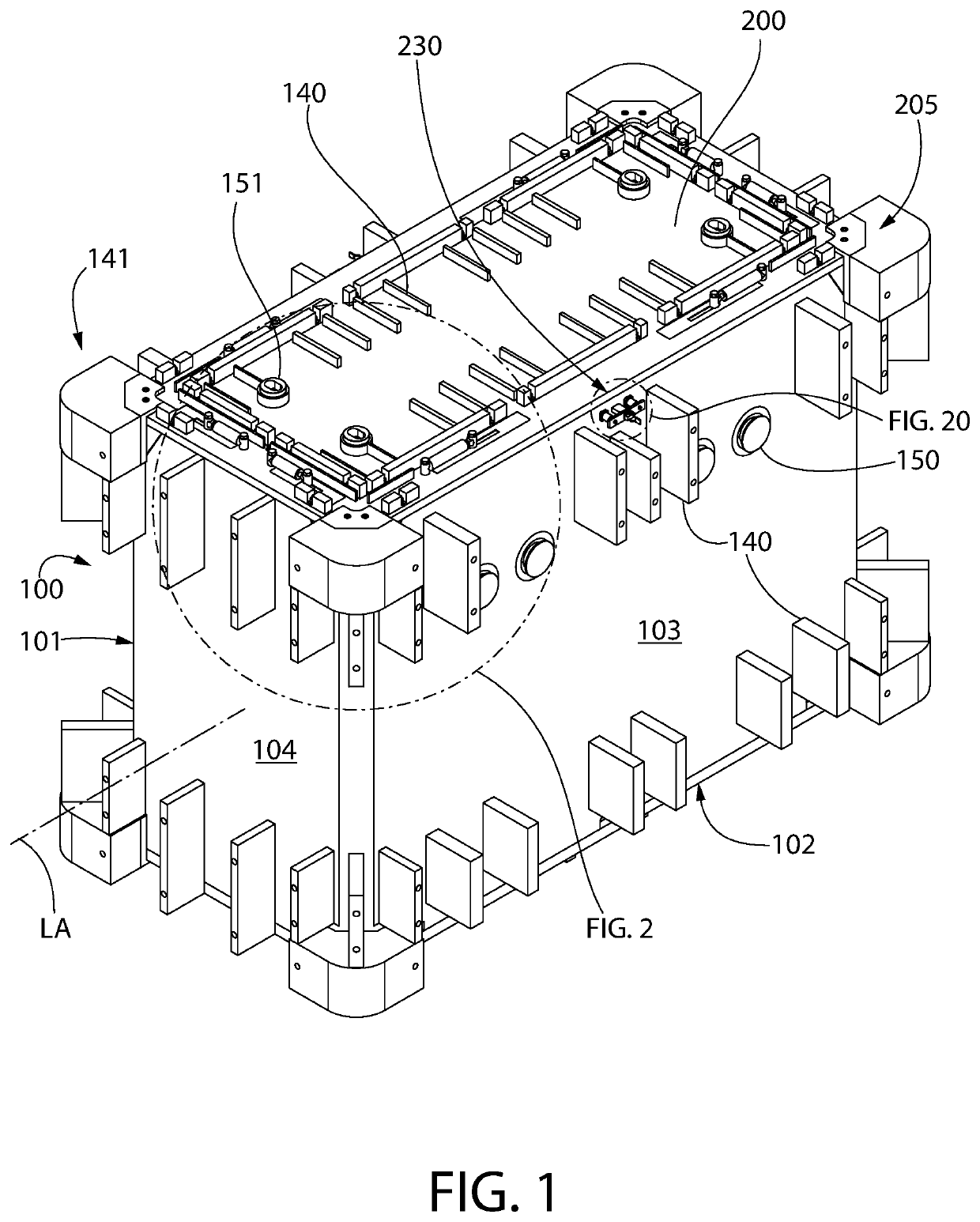
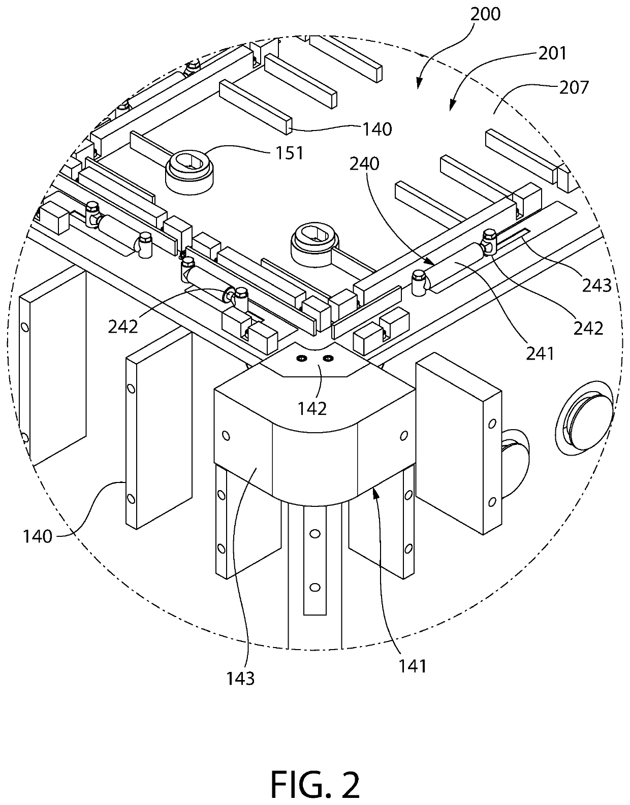
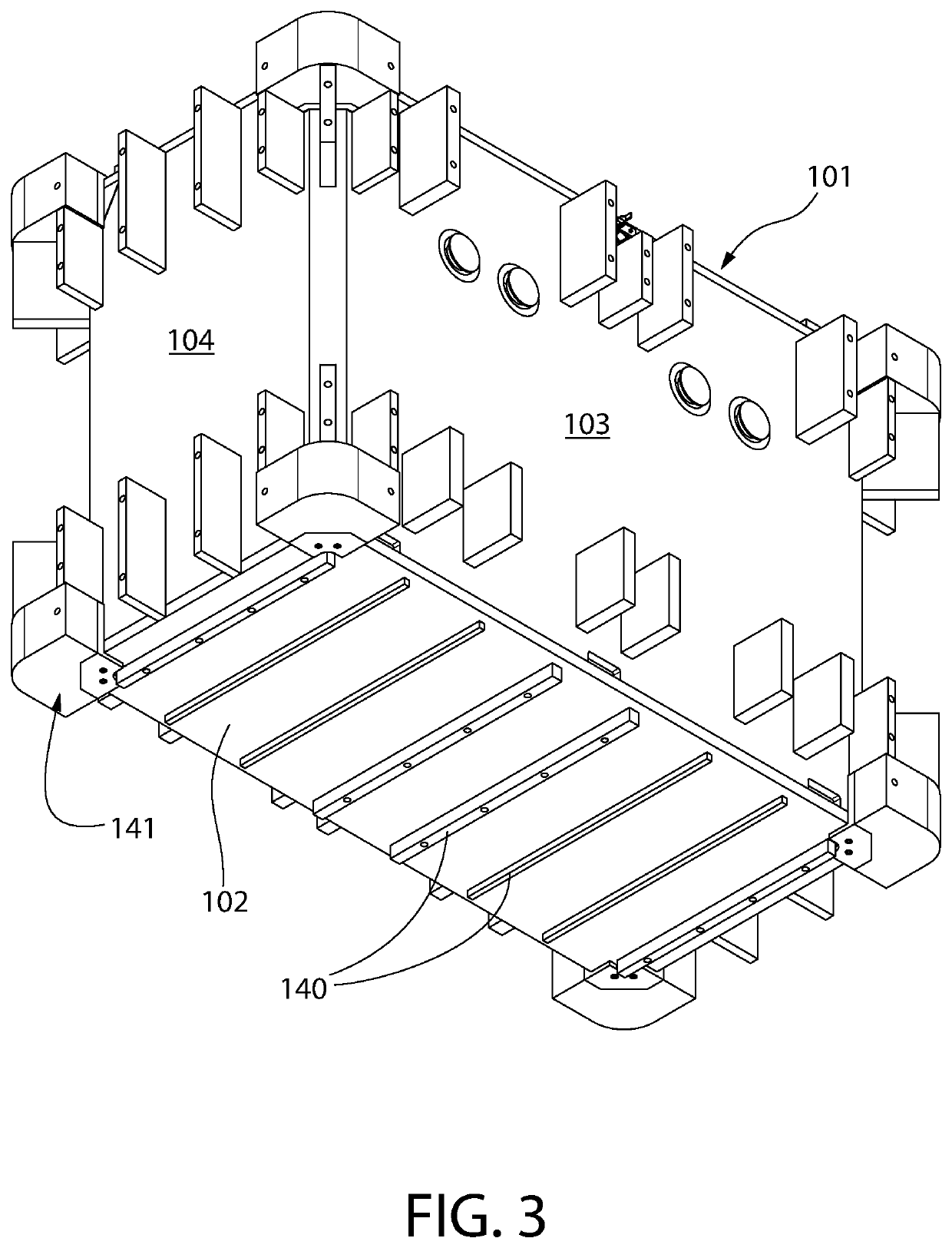
[0005]The present application provides a nuclear waste storage system comprising a radiation-shielded nuclear waste storage cask which overcomes the shortcomings of the foregoing cylindrical type storage casks described above for storing a wide variety of different nuclear waste materials. In one embodiment, a longitudinally elongated box-type cask is disclosed comprising an essentially rectangular body with rectilinear cross sectional internal storage cavity configured for holding nuclear waste material, and a matching rectangular closure lid. The elongated large top opening leading into the storage cavity extends for a majority of the longitudinal length of the cask. In contrast to the small circular opening at the top of cylindrical casks, the present rectangular opening allows large and irregular shaped radioactive metal pieces of waste material to be loaded inside the cask storage cavity in an efficient and expedient manner without undue handling by operating personnel, thereby reducing potential radiation dosage.

Problems solved by technology

Such a cask is inefficient to load all types of nuclear waste materials not limited to spent nuclear fuel into the cask.
The radiation waste materials are often too large and / or may be irregular shaped for insertion through the narrow top access opening in such cylindrical casks which leads to the internal storage cavity.
Further, the act of tightening the bolts once the cylindrical cask is packed with nuclear waste materials is a time consuming which exposes the workers to radiation dosage in proportion to the time needed to complete the tedious installation of the closure bolts.

Method used


Image

  • Storage and transport cask for nuclear waste
  • Storage and transport cask for nuclear waste
  • Storage and transport cask for nuclear waste

Examples


Embodiment Construction

[0048]The features and benefits of the invention are illustrated and described herein by reference to non-limiting exemplary (“example”) embodiments. This description of exemplary embodiments is intended to be read in connection with the accompanying drawings, which are to be considered part of the entire written description. Accordingly, the disclosure expressly should not be limited to such exemplary embodiments illustrating some possible non-limiting combination of features that may exist alone or in other combinations of features.

[0049]In the description of embodiments disclosed herein, any reference to direction or orientation is merely intended for convenience of description and is not intended in any way to limit the scope of the present invention. Relative terms such as “lower,”“upper,”“horizontal,”“vertical,”, “above,”“below,”“up,”“down,”“top” and “bottom” as well as derivatives thereof (e.g., “horizontally,”“downwardly,”“upwardly,” etc.) should be construed to refer to the...


PUM


Abstract

A nuclear waste cask in one embodiment includes an axially elongated cask body defining a longitudinally-extending opening forming an entrance to an internal storage cavity of the cask configured for holding radioactive nuclear waste materials. A closure lid detachably coupled to the cask body at the top opening seals the cavity. A cask locking mechanism includes a plurality of first locking protrusions spaced apart on the lid which are selectively interlockable with a plurality of second locking protrusions spaced apart on the cask body to lock the lid to the cask body. The first locking protrusions may be disposed on slideable locking bars moveable between locked and unlocked positions while the lid remains stationary on the cask body. Hydraulic or pneumatic actuators may be used to change position of the locking bars. The cask and lid may include other features such as impact absorbers and lifting elements.

Description

CROSS-REFERENCE TO RELATED APPLICATIONS[0001]This application claims the benefit of U.S. Provisional Application No. 62 / 979,640 filed Feb. 21, 2020, which is incorporated herein by reference in its entirety.BACKGROUND[0002]The present invention relates generally to systems and vessels for transporting and storing high level radioactive nuclear waste materials, and more particularly to a box-type cask in one embodiment for transport and storage of radioactive nuclear waste materials.[0003]The overpacks or casks used to store neutron activated metal and other radiated non-fissile high level radioactive waste, such as that resulting from operation nuclear power generation plants or other type facilities, is typically an open-top cylindrical structure with a bolted circular lid. Such a cask is inefficient to load all types of nuclear waste materials not limited to spent nuclear fuel into the cask. The radiation waste materials are often too large and / or may be irregular shaped for inser...

Claims


Application Information

Patent Timeline
Patent Type & Authority Patents(United States)
IPC IPC(8): G21F5/12
CPCG21F5/12G21F5/08Y02E30/30
Inventor SINGH, KRISHNA P.
Owner HOLTEC INT
Why Eureka
Try Eureka