Apparatus and method for coherent optical multiplexing 1+1 protection

a technology of coherent optical multiplexing and protection, applied in the direction of multiplex communication, instruments, optical elements, etc., can solve the problems of multiple optical channels failing, and affecting the operation of the network

Active Publication Date: 2022-06-28
II VI DELAWARE INC
View PDF4 Cites 3 Cited by
  • Summary
  • Abstract
  • Description
  • Claims
  • Application Information

AI Technical Summary

Benefits of technology

[0015]A method is disclosed for coherent optical multiplexing 1+1 protection of optical signals on disjoint paths. The method comprises operating in an add direction by: inputting, at each of a plurality of relay ports, first of the optical signals from a corresponding one of a plurality of multiplexers; splitting, at a first optical splitter, the first input optical signals from the plurality of relay ports to a plurality of transmission ports; and outputting the first split optical signals from each of the transmission ports on one of the disjoint paths. The method comprises operating in a drop direction by: inputting, at each of the transmission port, second of the optical signals from one of the disjoint paths; selecting, at an optical switch, the second optical signals input from one of the transmission ports; splitting, at a second optical splitter, the second selected optical signals from the optical switch to each of the relay ports; and outputting the second split optical signals from each of the relay ports to the corresponding one of the multiplexers.

Problems solved by technology

In a high-capacity optical network having wavelength-division-multiplexed (WDM) channels, an element of the network can fail.
For example, a fiber link may be cut, a node may fault, or other failure may occur.
In turn, this network failure will cause several optical channels to fail and data to be lost.
The conventional solutions for providing 1+1 protection has a problem that it is impossible to steadily ensure the signal transmission quality in the presence of relatively high insertion loss and multi-channel signal transmission.

Method used


Image

  • Apparatus and method for coherent optical multiplexing 1+1 protection
  • Apparatus and method for coherent optical multiplexing 1+1 protection
  • Apparatus and method for coherent optical multiplexing 1+1 protection

Examples


Embodiment Construction

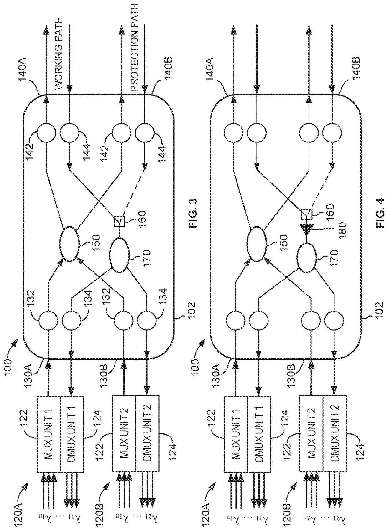
[0024]FIG. 3 schematically illustrates an apparatus 100 for providing coherent optical multiplexing 1+1 protection according to the present disclosure. As will be appreciated, the apparatus 100 is part of an optical network (not shown) and is used for dedicated path protection (also called 1+1 protection) to protect data should there be a failure in the network.

[0025]The apparatus 100 includes a plurality of multiplexers 120A-B and a node 102. The multiplexers 120A-B are multiplexing / demultiplexing units. In this arrangement, the apparatus 100 includes two multiplexing / demultiplexing units 120A-B, each of which includes one multiplexing sub-unit 122 and one demultiplexing sub-unit 124. Each unit 120A-B can connect with other components (not shown) of a network, such as used in an optical communication system. The node 102 has a plurality of relay ports 130A-B, a plurality of transmission ports 140A-B, a first optical splitter 150, an optical switch 160, and a second optical splitter...


PUM


Abstract

Coherent optical multiplexing 1+1 protection disclosed herein uses multiplexers, each having multiplexing and demultiplexing sub-units. Relay ports of a node are connected with the multiplexers, and each relay port is configured to input and output optical signals with the corresponding multiplexer. Two transmission ports of the node are connected with disjoint paths and are configured to input and output optical signals therewith. The node includes: a first optical splitter having input ports connected with the relay ports and two output ports connected with the two transmission ports; an optical switch connected with the transmission ports respectively via two input interfaces; a second optical splitter, which is a 1×N optical splitter, having one input port connected with an output interface of the optical switch and having output ports connected with the relay ports. The solution is reliable in implementation, has low insertion loss, and has good transmission performance.

Description

CROSS-REFERENCE TO RELATED APPLICATIONS[0001]This application claims the benefit under 35 U.S.C. 119 to Chinese Appl. No. 202010477314.6 filed 29 May 2020.FIELD OF THE DISCLOSURE[0002]The present disclosure relates to the technical field of an optical apparatus, and in particular, to an apparatus and a method for coherent optical multiplexing 1+1 protection.BACKGROUND OF THE DISCLOSURE[0003]In a high-capacity optical network having wavelength-division-multiplexed (WDM) channels, an element of the network can fail. For example, a fiber link may be cut, a node may fault, or other failure may occur. In turn, this network failure will cause several optical channels to fail and data to be lost. To protect data on the network, two copies of the data can be routed over disjoint paths using a technique called dedicated path protection (also called 1+1 protection). A link-disjoint backup path and wavelength are reserved for each primary path, and the backup wavelength is not shared with othe...

Claims


Application Information

Patent Timeline
Patent Type & Authority Patents(United States)
IPC IPC(8): H04J14/02G02B27/10
CPCH04J14/0202G02B27/1006H04B10/032H04B10/038H04J14/002H04J14/0294H04B10/291H04B10/614
Inventor HU, PEIGANGWANG, YAJUN
Owner II VI DELAWARE INC
Why Eureka
Try Eureka