Implanted electrical lead for pacemaker
a technology of electrical lead and pacemaker, which is applied in the field of medical devices, can solve the problems of lead failure substantially higher than that of transvenous, difficulty in implantation and maintenance of a permanent cardiac pacing system in children, and inability to provide a lead with a lifetime of this length,
- Summary
- Abstract
- Description
- Claims
- Application Information
AI Technical Summary
Problems solved by technology
Method used
Image
Examples
example 1
nalysis of Physical Properties of Open Helical Lead
[0037]The goal of initial experiments was to demonstrate the feasibility of our epicardial micropacemaker implantation method through a sheath placed percutaneously via subxyphoid approach into the pericardial space. In addition, we sought to document the nature of the connective tissue reaction due to the device and its open helical lead.
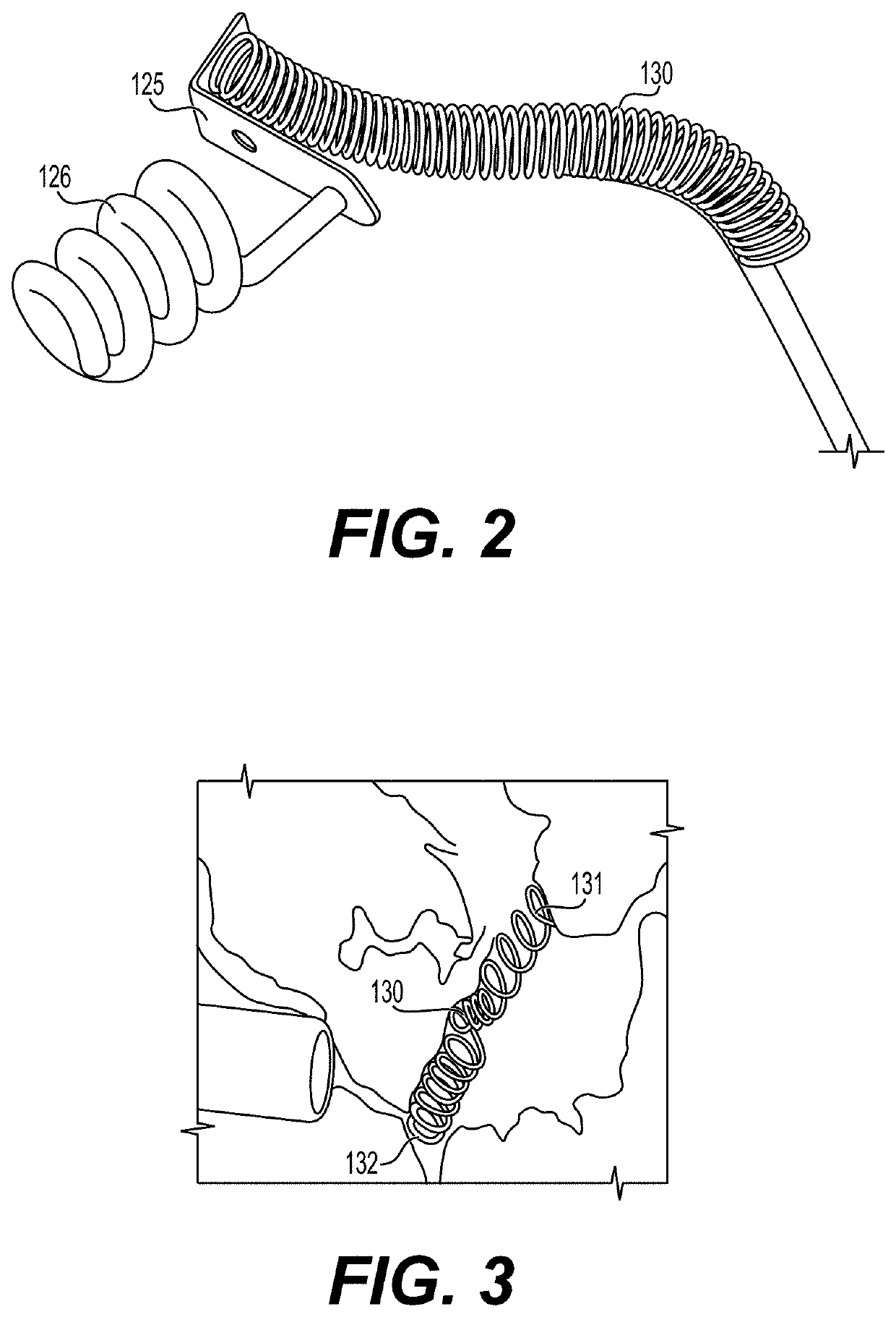
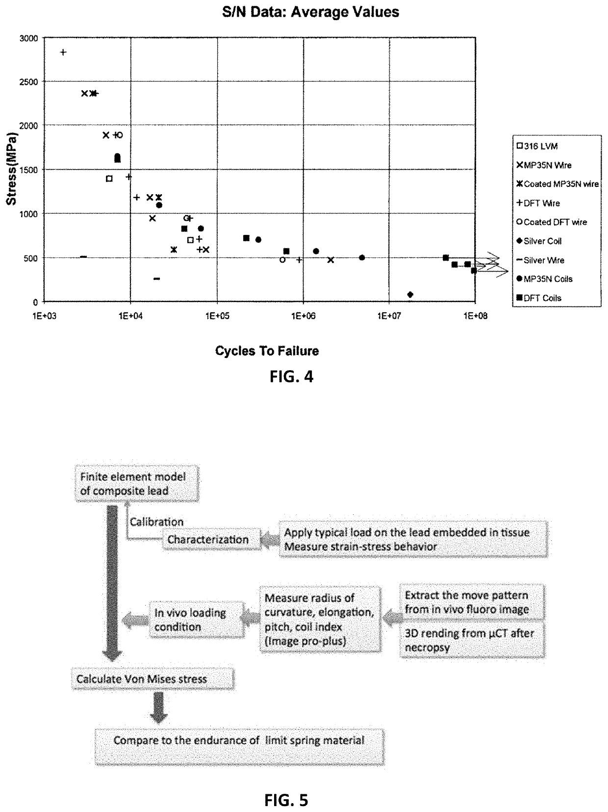
[0038]We designed, built, and implanted an epicardial micropacemaker in an adult pig (approximately 30 kg). Fluoroscopic images were recorded over 8 weeks of follow-up and just before necropsy. Biplane fluoroscopic imaging of the living animal was used to determine the relative motions of the helical turns in vivo with the assistance of Image Pro-Plus® software, which was programmed to automatically track the displacement of the two ends of the implanted open helical lead in a full cycle of motion in a single plane. From this, we computed the relative motion that is dissipated in the lead. Fluorosc...
example 2
cardial Implant Procedures
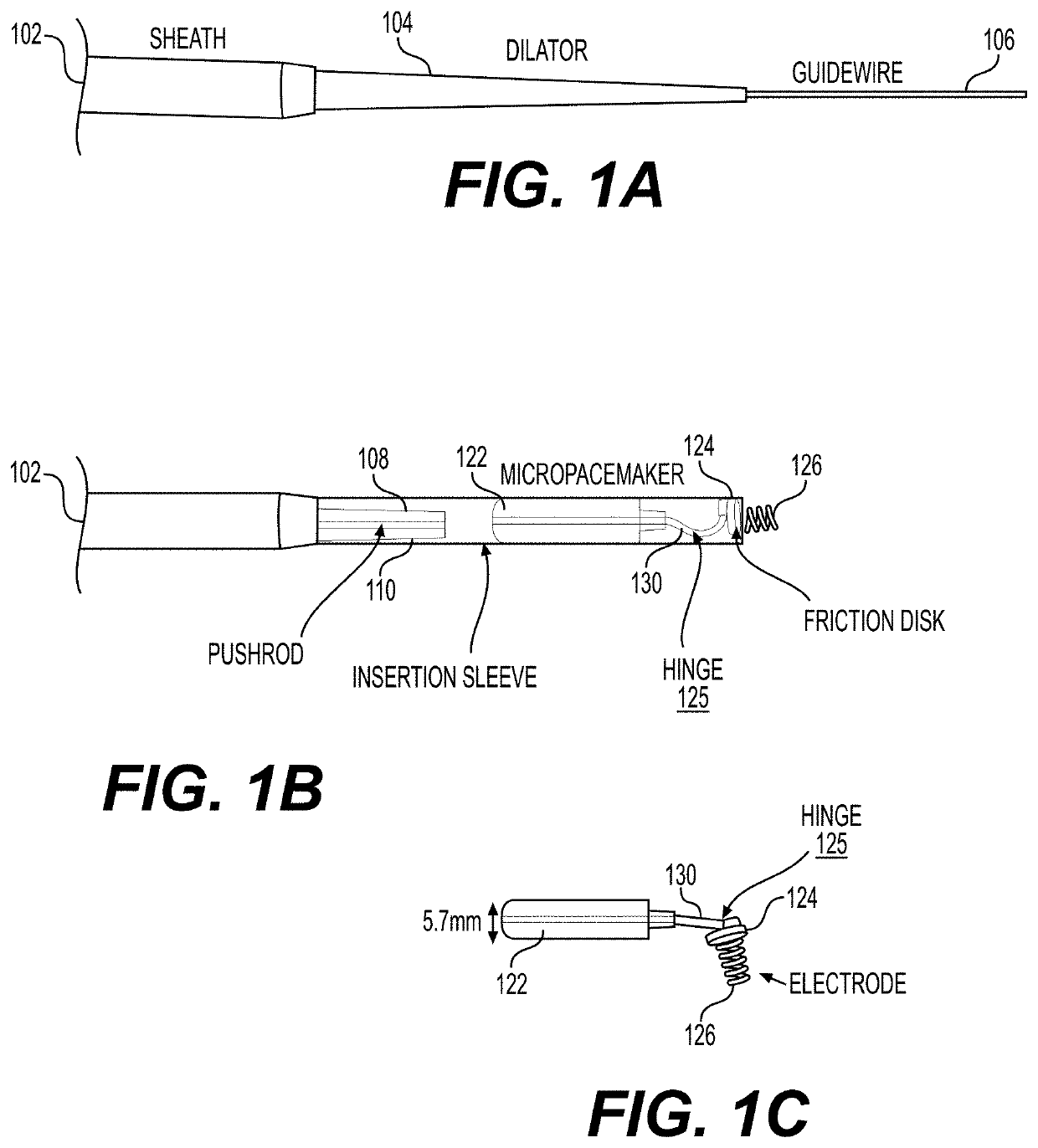
[0043]Due to the history of cardiac surgery in many pediatric and congenital heart disease patients, an intact and non-adherent pericardium is not present in many patients currently requiring epicardial pacemaker procedures. In embodiments, the targets for our epicardial micropacemakers are young children with congenital complete heart block who have not previously undergone thoracotomy and pericardial instrumentation. As a result, placing a wire 106 followed by dilator 104 and sheath 102 into the relatively free pericardial space is a valid approach. However, a large proportion of epicardial pacemakers are currently implanted in patients who have previously undergone pericardial instrumentation and are likely to have adherent or absent pericardial membranes. In order to address this group of patients, the epicardial micropacemakers can be implanted without entering the pericardial space. It appears that this is possible due to our ability to visualize tiss...
example 3
ion of Flexible Lead
[0044]During the minimally invasive implantation procedure, the open helical lead 130 must function as a combined hinge and spring, as illustrated in FIG. 1 where the open helical lead 130 is identified as performing the function of a hinge 125. At their point of mutual attachment within the friction disk 124, the open helical lead is oriented approximately perpendicularly to the axis of the helical electrode 126 that will be implanted into the myocardium from the epicardial surface. The open helical lead 130 is oriented parallel to the long axis of the cylindrical enclosure 122 that will contain the electronic circuitry of the pacemaker (here represented as a dummy epoxy cylinder 122). During implantation via the percutaneous sheath 102, the axes of the electrode 126 and circuitry enclosure 122 are held in parallel alignment by an insertion sleeve 102 that grips the friction disk 124 at its distal end. In this configuration, axial force and torque can be applied...
PUM
| Property | Measurement | Unit |
|---|---|---|
| thickness | aaaaa | aaaaa |
| diameter | aaaaa | aaaaa |
| tensile stress | aaaaa | aaaaa |
Abstract
Description
Claims
Application Information
 - R&D
- Intellectual Property
- Life Sciences
- Materials
- Tech Scout
- Unparalleled Data Quality
- Higher Quality Content
- 60% Fewer Hallucinations
Browse by: Latest US Patents, China's latest patents, Technical Efficacy Thesaurus, Application Domain, Technology Topic, Popular Technical Reports.
© 2025 PatSnap. All rights reserved.Legal|Privacy policy|Modern Slavery Act Transparency Statement|Sitemap|About US| Contact US: help@patsnap.com


