Magnetic resonance imaging apparatus and control program therefor

a magnetic resonance imaging and control program technology, applied in the direction of measuring using nmr, instruments, diagnostic recording/measuring, etc., can solve the problems of affecting the smooth examination, and limiting the automatic calculation

Active Publication Date: 2022-07-05
FUJIFILM HEALTHCARE CORP
View PDF10 Cites 0 Cited by
  • Summary
  • Abstract
  • Description
  • Claims
  • Application Information

AI Technical Summary

Benefits of technology

[0009]The invention has been made in view of the above circumstances, and it is an object of the invention to make it possible to perform imaging at the center of an image regardless of a subject as shown in FIG. 12B by optimizing scan parameters before image capturing and accordingly to reduce a burden on the user due to manual operation and to prevent the extension of the examination time due to re-imaging, thereby improving the examination efficiency.
[0013]According to the invention, the offset amount and various scan parameters for each subject are calculated, and the calculation results are automatically reflected in the imaging to prevent the imaging time from being extended by optimizing the imaging position. In addition, by eliminating the manual operation of the user, the work burden is reduced. By shortening the time and reducing the work burden, the examination efficiency can be improved.

Problems solved by technology

In addition, in the case of improper adjustment, there is a possibility of re-imaging, which interferes with a smooth examination.
However, the above technique described in JP-A-2017-113164 is limited to automatically calculating some (ratio of rectangular field of view) of scan parameters from a positioning image (a scanogram or a scout image) or a dedicated pre-scan image.
Therefore, the calculation accuracy of the scan parameter depends on the accuracy of the position of the positioning image or the dedicated pre-scan image, and re-imaging cannot be avoided when the offset of the subject with respect to the FOV is large.
In addition, with the development of new technology such as a function of automatically moving the bed into the gantry and automatically stopping the bed at the position of the examination part, as shown in FIG. 12A, the failure of imaging due to mismatch between the set position of the subject and the imaging position registered in advance in the apparatus and the re-capturing of images due to the imaging failure increase.
In addition to this, there is a problem that the examination efficiency is lowered when a re-imaging operation is performed at the time of failure of the setting of the subject imaging conditions or the capturing of a positioning image.

Method used


Image

  • Magnetic resonance imaging apparatus and control program therefor
  • Magnetic resonance imaging apparatus and control program therefor
  • Magnetic resonance imaging apparatus and control program therefor

Examples


Embodiment Construction

[0026]Hereinafter, an MRI apparatus according to an embodiment of the invention will be described with reference to the diagrams. In addition, in all the diagrams for describing the embodiment of the invention, those having the same function are denoted by the same reference numerals, and the repeated description thereof will be omitted.

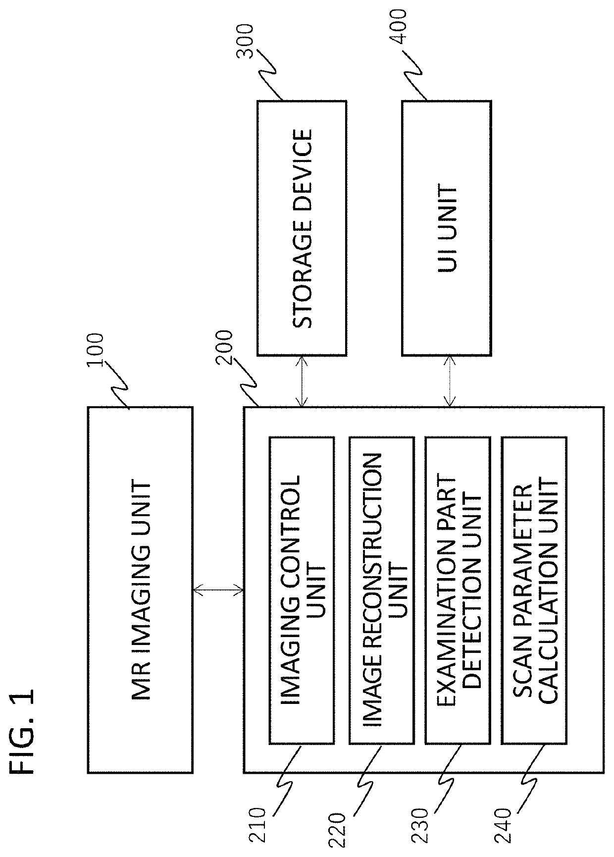
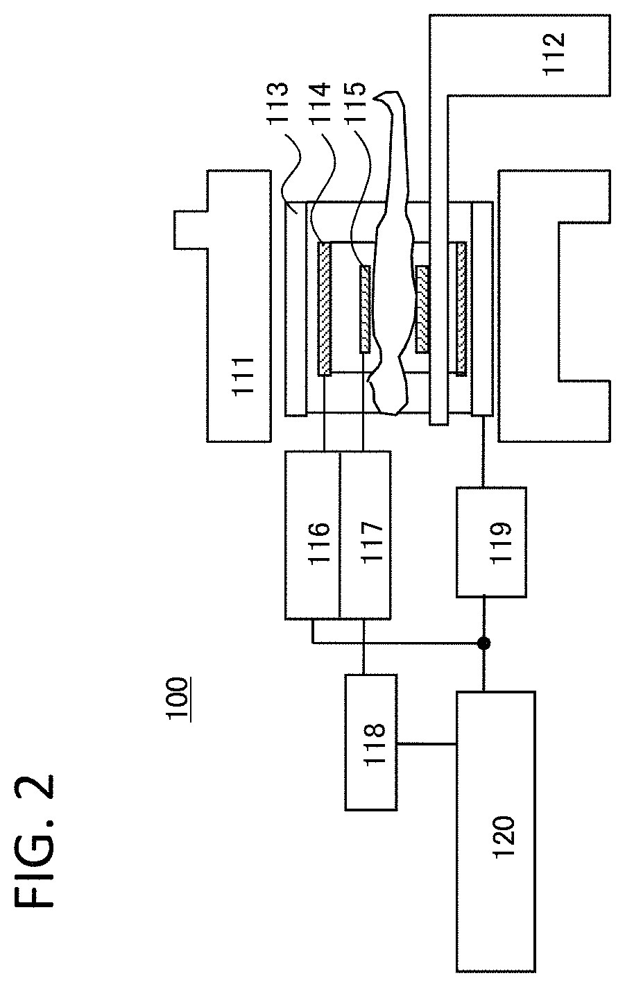
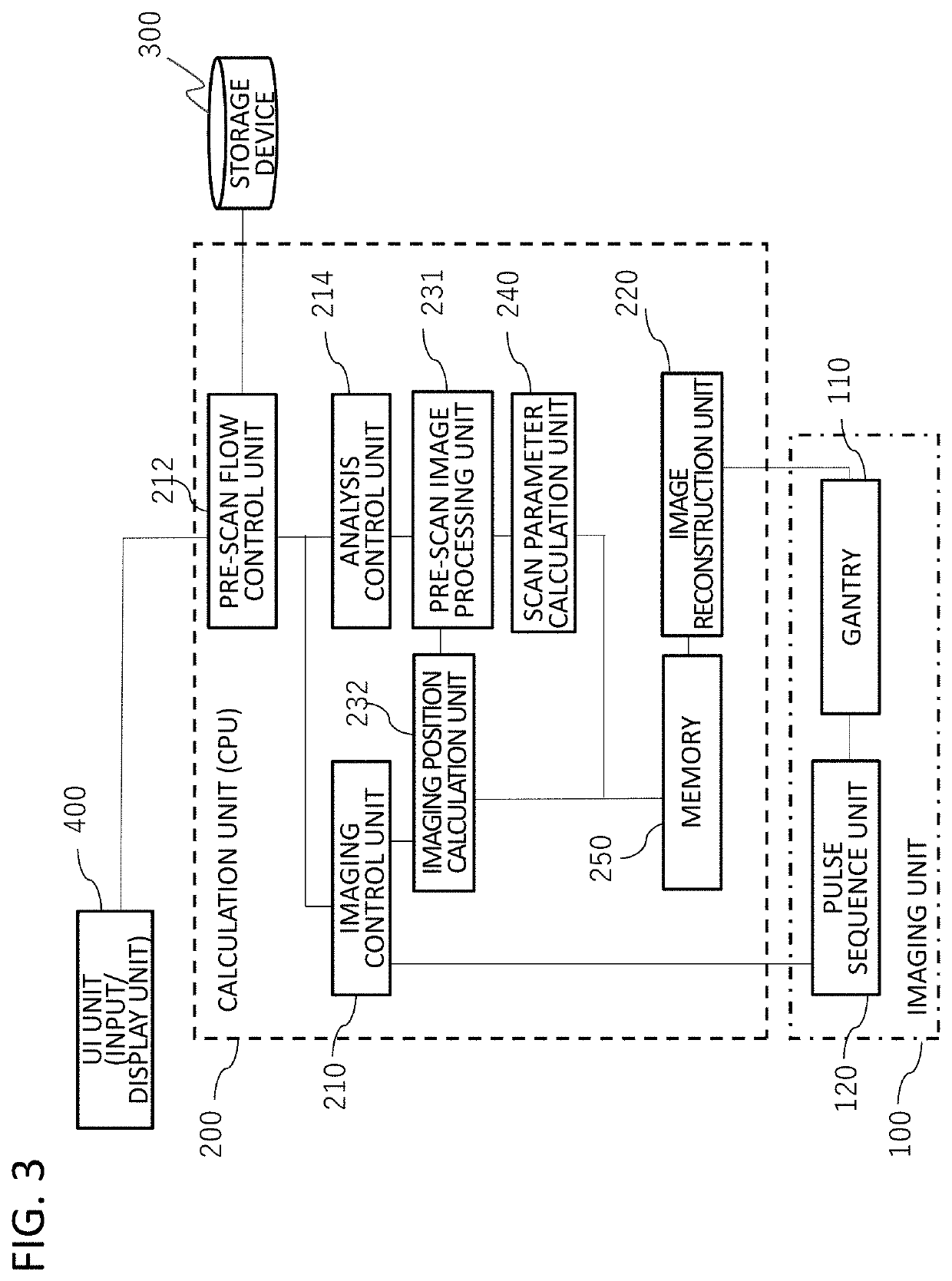
[0027]As shown in FIG. 1, the MRI apparatus of the present embodiment mainly includes: an imaging unit 100 that generates nuclear magnetic resonance in a subject and collects an NMR signal; a calculation unit 200 that controls the operation of the imaging unit 100 and performs various calculations including image reconstruction using the NMR signal collected by the imaging unit 100; a storage device 300 that stores data required for the processing of the imaging unit 100 or the calculation unit 200, processing results, and the like; and a user interface (UI) unit 400 that receives a command or condition settings from the user.

[0028]The configuration ...


PUM


Abstract

Imaging failure of a positioning image due to the difference in the position or the size of a subject placed in the examination space is prevented, and accordingly, the extension of the examination time is prevented. A pre-scan for appropriately setting the imaging position for positioning imaging is automatically performed prior to the positioning imaging and the main imaging of an MRI apparatus, and a region where an examination part of a subject is present (the extent of the examination part) is detected using the measurement data. By using the detected extent of the examination part, it is possible to subsequently determine the imaging position or calculate the scan parameters used for imaging.

Description

INCORPORATION BY REFERENCE[0001]The present application claims priority from Japanese patent application JP-2020-087679 filed on May 19, 2020, the content of which is hereby incorporated by reference into this application.BACKGROUND OF THE INVENTIONField of the Invention[0002]The present invention relates to a magnetic resonance imaging apparatus and a control program therefor.Description of the Related Art[0003]A magnetic resonance imaging (hereinafter, referred to as MRI) apparatus is an apparatus that measures a nuclear magnetic resonance (NMR) signal generated by nuclear spins forming the tissues of a subject, especially, the human body, and images the shapes or tissues of the head, abdomen, limbs, and the like in a two-dimensional or three-dimensional manner.[0004]In an examination using the MRI apparatus, an anatomically determined cross section is usually imaged for each examination target part, but the body shape of the subject or the posture on the bed is different for each...

Claims


Application Information

Patent Timeline
Patent Type & Authority Patents(United States)
IPC IPC(8): G01R33/54G01R33/56
CPCG01R33/543G01R33/5608A61B5/055A61B5/0037G01R33/56545
Inventor IKEGAWA, AYAKATAKIZAWA, MASAHIRONAGAO, HISAKOGOTOU, TOMOHIRO
Owner FUJIFILM HEALTHCARE CORP
Why Eureka
Try Eureka