Supercharge Your Innovation With Domain-Expert AI Agents!

Compressor

a compression part and compressor technology, applied in the field of compressors, can solve the problems of scroll tilting enough to deteriorate compression efficiency and reliability disadvantageously, scroll vibration or upsetting moment can be damped, and the acting points of gas power and reaction match on the shaft can be affected

Active Publication Date: 2022-07-12
LG ELECTRONICS INC
View PDF12 Cites 0 Cited by
  • Summary
  • Abstract
  • Description
  • Claims
  • Application Information

AI Technical Summary

Benefits of technology

The solution effectively induces all refrigerant from the compression part to the drive part, enhances durability by preventing damage from vibration, and maximizes the sealing effect, thereby improving compression efficiency and reliability.

Problems solved by technology

The compression part is provided higher than the drive part to be closer to the discharging part such that the conventional scroll compressor may have a difficulty in supplying oil to the compression part.
Also, the conventional scroll compressor disadvantageously requires a lower frame to support the shaft connected to the compression part from a lower area of the drive part.
A gas power generated by the refrigerant in the scroll compressor will not match with the reaction supporting the gas power such that the scroll could tilt enough to deteriorate compression efficiency and reliability disadvantageously.
In addition, when the shaft penetrates the compression part in the lower scroll compressor, acting points of the gas power and the reaction match on the shaft and scroll vibration or upsetting moment can be damped.
However, while being drawn into the drive part via the compression part, the refrigerant might be discharged towards an inner circumferential surface of the case by a centrifugal force disadvantageously.
Moreover, the oil discharged from the compression part while flowing towards the drive part might also leak towards the case, without being drawn into the drive part.
If some of such the refrigerant leaks between the drive part and the compression part, without being supplied to the discharging part, the performance of the compressor might deteriorate disadvantageously.
In addition, even if an additional closing member is provided in the drive part or the compression part to prevent leakage of oil or refrigerant, the conventional lower scroll compressor is more likely to be damaged by the strong vibration generated in the compression part.
Also, the closing member is not fixed in the conventional lower scroll compressor such that the oil or refrigerant might still leak.
The additional closing member provided in the compressor to prevent the refrigerant or oil leakage might be interfered with the drive part and the inference might deteriorate the durability or the closing member spaced apart from the drive part could not guarantee a sealing effect.

Method used


Image

  • Compressor
  • Compressor
  • Compressor

Examples


Embodiment Construction

[0047]Reference will now be made in detail to the embodiments of the present disclosure, examples of which are illustrated in the accompanying drawings. Wherever possible, the same reference numbers will be used throughout the drawings to refer to the same or similar parts. A singular expression may include a plural expression unless otherwise stated in the context. In the following description, a detailed description of related known configurations or functions incorporated herein will be omitted to avoid obscuring the subject matter. The accompanying drawings illustrate the exemplary embodiments of the present disclosure. The exemplary embodiments of the present disclosure are merely provided to describe the present disclosure in detail, and the technical range of the present disclosure is not limited by the exemplary embodiments.

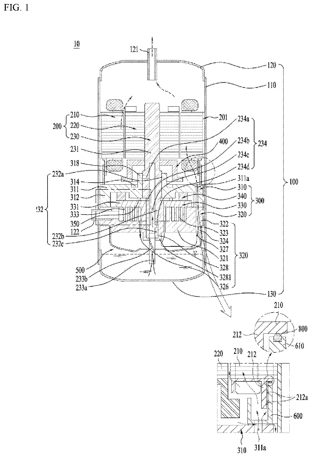
[0048]FIG. 1 is a view illustrating the principal components of a lower scroll compressor 10 and functions of a separator according to the embodiment of ...


PUM


Abstract

There is disclosed a compressor comprising a case comprising a discharging part provided one side and configured to discharge a refrigerant, the case defining a predetermined space for storing oil; a drive part comprising a rotor coupled to an inner circumferential surface of the case and having coils wound there around and configured to generate a rotation magnetic field, and a rotor mounted in the rotor and configured to be rotatable by the rotation magnetic field; a shaft extending in a state of being coupled to the rotor; a compression part lubricated by the oil in a state of being coupled to the shaft and configured to compress and discharge the refrigerant; and a sealing part extending from the stator towards the compression part and configured to induce the winding of the coil.

Description

CROSS-REFERENCE TO RELATED APPLICATIONS[0001]This application claims priority to Korean Patent Application No. 10-2018-0131195, filed on Oct. 30, 2018, the entire contents of which is hereby incorporated by reference in its entirety.BACKGROUND OF THE DISCLOSUREField of the Disclosure[0002]Embodiments of the present disclosure relate to a compressor, more particularly, a compressor including a sealing part configured to maintain durability and a sealing ability, while preventing a refrigerant and oil from leaking between a compression part and a drive part.Background of the Disclosure[0003]Generally, a compressor is a mechanism that is applied to a freezing cycle of a refrigerator or an air conditioner (hereinafter, a freezing cycle) and configured to cause heat-exchange in such a freezing cycle by compressing a refrigerant.[0004]The compressor may be categorized based on a method for compressing the refrigerant into a reciprocating compressor, a rotary compressor, a scroll compresso...

Claims


Application Information

Patent Timeline
Patent Type & Authority Patents(United States)
IPC IPC(8): F04D29/12F04D29/10F04D29/063F04D5/00F04D29/049F16J15/34F04D29/62F04D31/00F04D29/046F04D29/08
CPCF04D29/102F04D5/00F04D5/002F04D5/007F04D29/046F04D29/049F04D29/0462F04D29/063F04D29/08F04D29/12F04D29/126F04D29/626F04D31/00F16J15/34F04C18/0215F04C23/02F04C23/008F04C27/00F04C29/02F04C29/06F04C29/028F04C29/0028F04C29/065
Inventor LEE, KANGWOOKJEON, NAYOUNGKIM, CHEOLHWAN
Owner LG ELECTRONICS INC
Features
  • R&D
  • Intellectual Property
  • Life Sciences
  • Materials
  • Tech Scout
  • Unparalleled Data Quality
  • Higher Quality Content
  • 60% Fewer Hallucinations
Learn More