
Surveying instrument

a technology of surveying instruments and instruments, applied in the field of surveying instruments, can solve the problems of time and skill, complicated installation work of surveying instruments,

Active Publication Date: 2022-07-12
KK TOPCON
View PDF17 Cites 0 Cited by
  • Summary
  • Abstract
  • Description
  • Claims
  • Application Information

AI Technical Summary

Benefits of technology

[0005]It is an object of the present invention to provide a surveying instrument which can be easily installed in a short time.
[0014]According to the present invention, the surveying instrument including a tripod which is installed on an installation surface and a surveying instrument main body which is provided on the tripod and laterally rotatable around a longitudinal axis, wherein the tripod includes a base module, a reference leg which is integral with the base module and has a known relationship between a lower end of the reference leg and a machine reference point which is a machine center of the surveying instrument main body, and two auxiliary legs, wherein the surveying instrument main body includes a distance measuring module configured to measure a distance to an object to be measured, a lateral rotation angle detector configured to detect a lateral rotation angle of the surveying instrument main body, and an arithmetic control module, the reference leg is installed in such a manner that a lower end of the reference leg coincides with a reference point, and the arithmetic control module configured to calculate a position of the machine reference point with respect to the reference point based on the positional relationship between the lower end of the reference leg and the machine reference point. As a result, performing the installation in such a manner that the lower end of the reference leg can coincide with the reference point can suffice at the time of the installation work, and the installation work can be easily carried out in a short time.

Problems solved by technology

For this reason, a surveying instrument installation work is complicated and requires a time and a skill.

Method used


Image

  • Surveying instrument
  • Surveying instrument
  • Surveying instrument

Examples


first embodiment

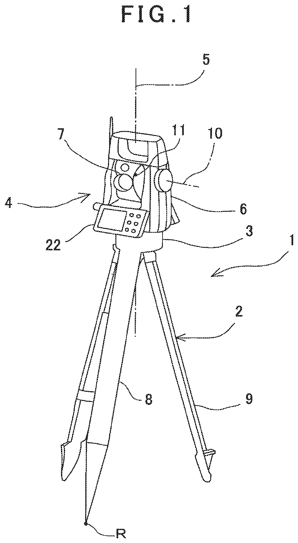
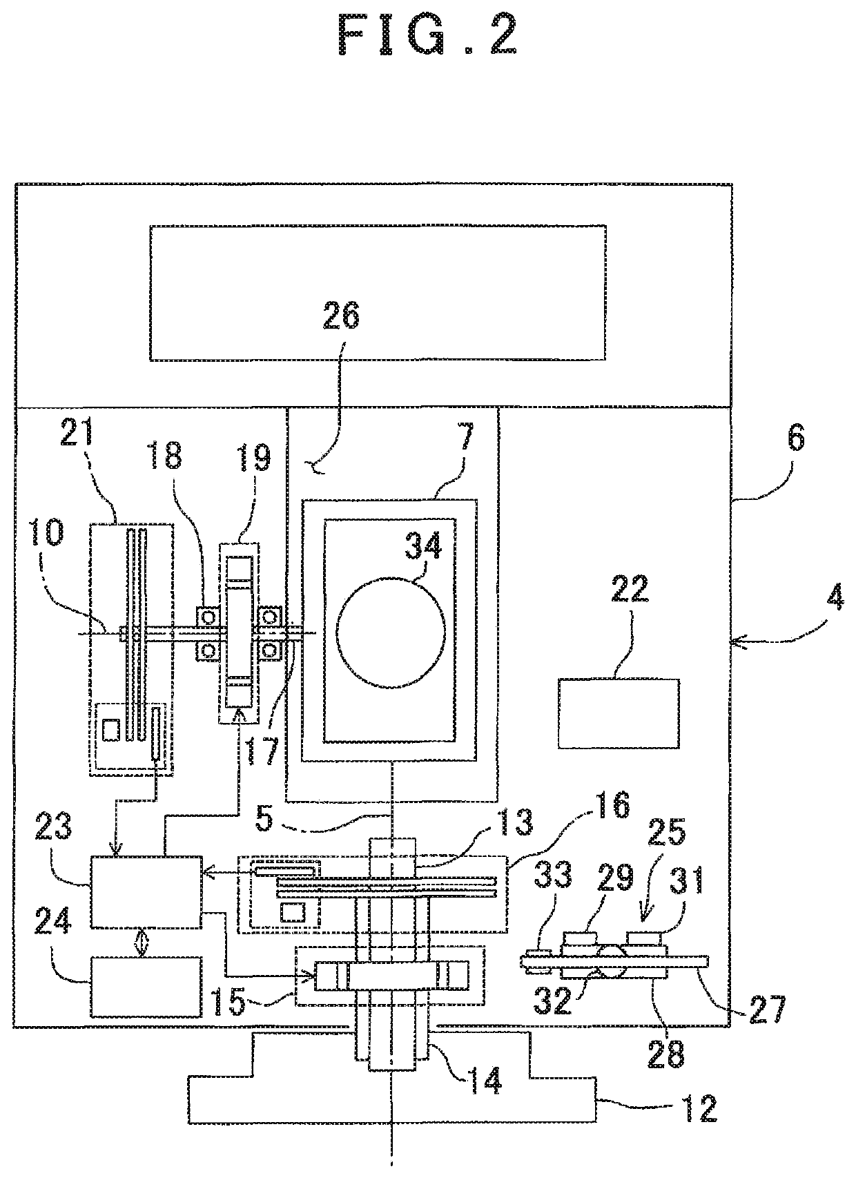
[0022]First, in FIG. 1 and FIG. 2, a surveying instrument according to the present invention will be described.

[0023]A surveying instrument 1 is a total station, for instance. The surveying instrument 1 has mainly a tripod 2, a base module 3 provided the tripod 2, and a surveying instrument main body 4 provided on the base portion 3. The surveying instrument main body 4 is mainly constituted of a frame unit 6 provided to the base module 3 so that it can laterally rotate around a longitudinal axis 5 and a telescope module 7 provided to the frame unit 6 so that it can longitudinally rotate around a lateral axis 10.

[0024]Further, the tripod 2 is constituted of a reference leg 8 integrally molded with the base module 3 and two auxiliary legs 9 provided with respect to the base module 3 so that it can rotate (tilt) around a base end portion at a predetermined angle. A lower end of the reference leg 8 has a sharp tip, and the tripod 2 is installed in such a manner that the lower end of th...

second embodiment

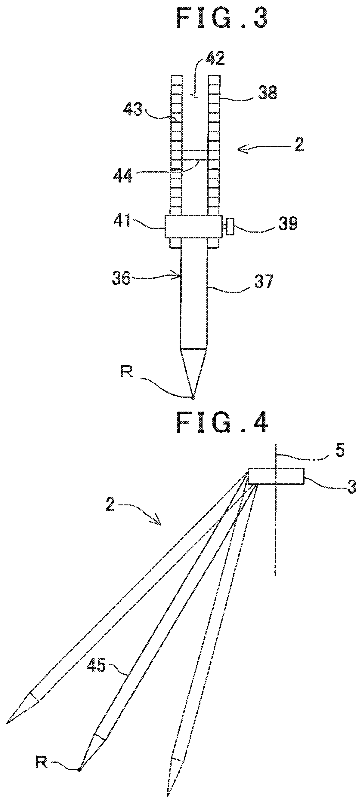
[0066]In the second embodiment, a reference leg 36 of a tripod 2 is expansible or contractible. The reference leg 36 has a rod-like leg portion 37 whose lower end has a sharp tip, a cylindrical holding portion 38 which slidably holds the leg portion 37, and a fixing portion 41 which is provided to the holding portion 38 and fixes a position of the leg portion 37 by fastening a screw 39 or by screwing the screw 39 into a screw hole (not shown) formed in the leg portion 37.

[0067]A slot 42 which is long in an axial direction is formed in the holding portion 38, and the scale 43 are formed on a sidewall of the slot 42 at the predetermined intervals, for instance. Further, a reference line 44 is formed at a predetermined position on a base end part of the leg portion 37.

[0068]When the leg portion 37 is slid with respect to the holding portion 38, a length of the reference leg 36 is adjusted. Further, when the reference leg 36 is expanded or contracted, a direction of the surveying instru...

third embodiment

[0083]In the third embodiment, the tilt direction of the reference leg 45 with respect to the reference direction does not change irrespective of a direction or an attitude of the surveying instrument main body 4, and the tilt angle of the reference leg 45 with respect to the longitudinal axis 5 is known. That is, in a state where the surveying instrument 1 is installed, the reference leg 45 and the base module 3 have a known relationship.

[0084]Therefore, since just installing the surveying instrument 1 in such a manner that the lower end of the reference leg 45 coincides with the reference point R, the arithmetic control module 23 enables acquiring the position of the machine reference point 11 with respect to the reference point R and measuring the three-dimensional coordinates of the object to be measured, the leveling work is no longer necessary, the installation work can be facilitated, and a work time can be shortened.

[0085]It is to be noted that, in the third embodiment, the ...


PUM


Abstract

There is provided a surveying instrument including a tripod which is installed on an installation surface and a surveying instrument main body which is provided on the tripod and laterally rotatable around a longitudinal axis, wherein the tripod includes a reference leg has a known relationship between a lower end of the reference leg and a machine reference point which is a machine center of the surveying instrument main body, and two auxiliary legs, the reference leg is installed in such a manner that a lower end of the reference leg coincides with a reference point, wherein the surveying instrument main body calculates a position of the machine reference point with respect to the reference point based on the positional relationship between the lower end of the reference leg and the machine reference point.

Description

BACKGROUND OF THE INVENTION[0001]The present invention relates to a surveying instrument which can be easily installed.[0002]In case of performing a survey using a surveying instrument, the surveying instrument must be first installed on a reference point which becomes a reference for the survey.[0003]Generally, in case of installing the surveying instrument on the reference point, the surveying instrument is installed by using a tripod. Conventionally, a machine center of the surveying instrument must be accurately positioned on a vertical line running through the reference point, and then the surveying instrument must be horizontally leveled up by using a leveling device.[0004]Further, for instance, a point having the known three-dimensional coordinates must be measured by the surveying instrument so that a height from the reference point to the machine center (a machine height of the surveying instrument) can be measured. For this reason, a surveying instrument installation work ...

Claims


Application Information

Patent Timeline
Patent Type & Authority Patents(United States)
IPC IPC(8): G01C3/02G01B21/22G01C15/14G01C3/10
CPCG01C3/02G01B21/22G01C3/10G01C15/14G01C15/008
Inventor NISHITA, NOBUYUKIOHTOMO, FUMIO
Owner KK TOPCON
Learn More