Selective plane illumination in the conventional inverted microscope geometry by side illumination

a technology of inverted microscope and side illumination, applied in the field of microscopy, can solve the problems of large immersion volume, increase the amount of reagents needed, and no separation of optics and samples, and achieve the effects of maximizing field of view, high throughput, and stable mounting

Active Publication Date: 2022-07-12
RGT UNIV OF CALIFORNIA
View PDF4 Cites 0 Cited by
  • Summary
  • Abstract
  • Description
  • Claims
  • Application Information

AI Technical Summary

Benefits of technology

[0008]Other embodiments include a imaging apparatus comprising a microscope, and a device comprising a side illumination unit, a two window sample chamber, and a refractive index matching. In another embodiment, the apparatus is capable of imaging thick samples, such as cells, tissues, or small organisms embedded in a hydrogel. In another embodiment, the apparatus is capable of imaging a monolayer of cells. In another embodiment, the imaging apparatus further comprises a fluorescence lifetime measurement capability. In another embodiment, the side illumination unit comprises components to generate a light sheet illuminating on a sample. In another embodiment, the two window sample chamber comprises two optically transparent windows perpendicular to each other. In another embodiment, the two window sample chamber further comprises a magnetic attachment to ensure easy to handle, stable, and reproducible mounting of a sample. In another embodiment, the refractive index matching comprises raising a sample in the two window sample chamber using an optically transparent material with a refractive index identical to the sample immersion fluid. In another embodiment, the refractive index matching allows imaging of flat samples such as a monolayer of cells. In another embodiment, the observation plane is parallel to the sample surface, maximizing field of view for flat samples. In another embodiment, the microscope is an inverted or standard research microscope. In another embodiment, the imaging apparatus is coupled with a microfluidic device. In another embodiment, the imaging apparatus is coupled with high throughput 3D imaging of multiple samples.

Problems solved by technology

However, the arrangement of two objective lenses perpendicular to each other provides a number of challenges in terms of instrument design and sample geometry.
The drawbacks of this geometry include the requirement of a large sample container to accommodate both lenses resulting in a large immersion volume.
This can cause sample disturbance due to flow / convection and increases the amount of reagents needed.
Further, there is no isolation of optics and sample which is problematic when dealing with hazardous samples (toxic, cancerous, infectious, etc.).
Finally, since the observation plane is at an angle with respect to the sample container, the field of view for flat samples, such as a monolayer of cells, is limited, i.e., the full field of view of the detector cannot be utilized.

Method used


Image

  • Selective plane illumination in the conventional inverted microscope geometry by side illumination
  • Selective plane illumination in the conventional inverted microscope geometry by side illumination
  • Selective plane illumination in the conventional inverted microscope geometry by side illumination

Examples


example 1

Generally

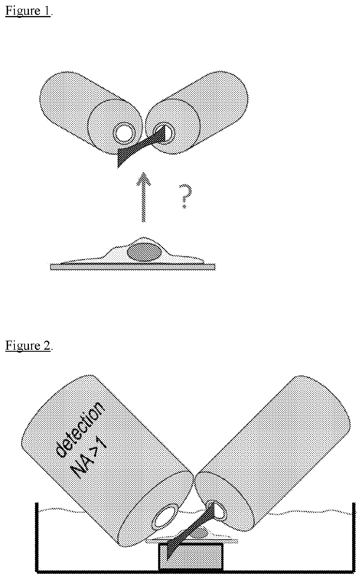
[0050]Selective plane illumination microscopy (SPIM) is one of the most suitable techniques for fast, three-dimensional imaging. By confining the excitation light to a sheet, SPIM combines axial sectioning capability with minimal light exposure and fast, camera-based image acquisition. SPIM typically uses two (objective) lenses arranged perpendicular to each other. One lens is used for light detection, while the focal plane of that lens is illuminated with a sheet of light generated via the other lens. To generate the light sheet, cylindrical optics can be used. Alternatively, the beam can be rapidly scanned across the field of view of the detection lens to generate the sheet illumination. However, the arrangement of two objective lenses perpendicular to each other provides a number of challenges in terms of instrument design and sample geometry as explained in the following.

[0051]Initially SPIM was designed around the specimen with excitation and detection in the horizonta...

example 2

Components of SideSPIM

[0054]In one embodiment, the three key components of the sideSPIM include:

[0055]1) Side illumination unit. All optical components required to generate the light sheet illuminating the sample are mounted onto a single platform. This unit can be coupled to any inverted microscope.

[0056]2) Two window sample chamber. With two optically transparent windows perpendicular to each other, the light to generate the sheet illumination at the sample plane can be introduced from the side. Magnetic attachment of the chamber to the microscope stage ensures easy to handle, stable and reproducible mounting.

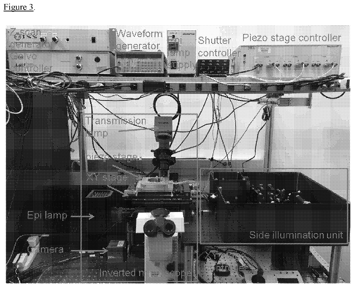
[0057]3) Refractive index matching. By raising the sample inside the chamber well using an optically transparent material with a refractive index identical to the sample immersion fluid, samples can be imaged distortion free all the way to the bottom. Index matching also allows imaging of flat samples such as a monolayer of cells in the first place.

example 3

Side Illumination Unit

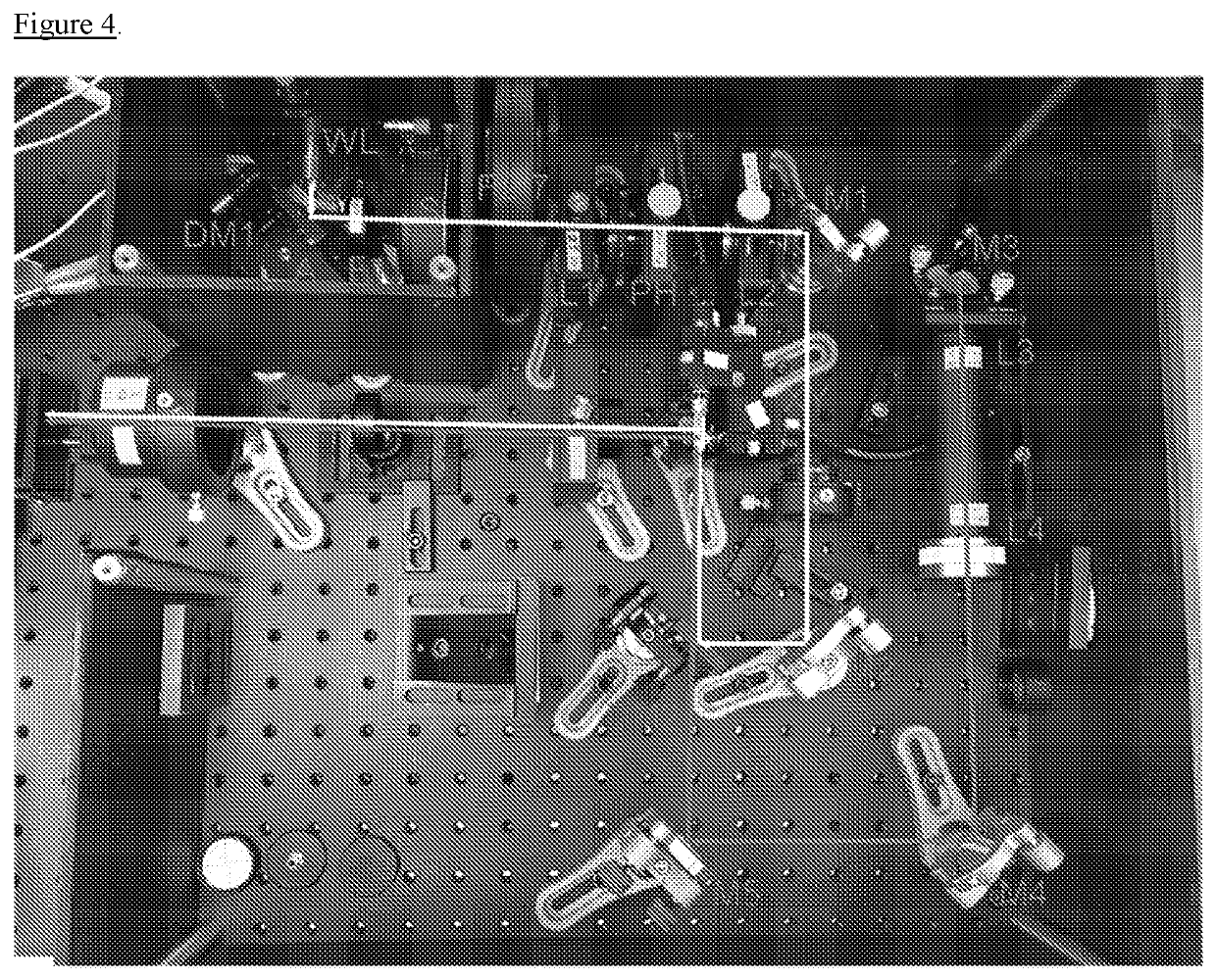
[0058]One embodiment of the sideSPIM prototype is illustrated in FIG. 3. The system is based on an inverted microscope (IX71 fitted with epifluorescence illumination unit, Olympus) with camera detection (Edge 4.2, PCO). A motorized xy stage (MS-2000, ASI) holds a piezo xyz-stage (NANO-PDQ375, Mad City Labs) fitted with a custom magnetic sample holder inset. The stage assembly is raised by 36 mm using spacers to make room for the objective lens of the side illumination unit located on the left. Besides being installed onto the same flat and rigid mounting surface (Smart Table UT2, Newport), no further mechanical connections from to side illumination unit to the microscope body are required. A more detailed view of the side illumination assembly is shown in FIG. 4.

[0059]With this unit, the light sheet is generated and injected into the sample. The assembly consists of a white laser source, WL (SC 390, Fianium), for excitation with visible light. From the fiber ou...


PUM


Abstract

A sample imaging device includes a side illumination unit, a two window sample chamber, and refractive index matching. An optically transparent sample holder is in the sample well as is sample immersion fluid. The refractive index matching includes matching of the refractive index of material of a sample to be imaged.

Description

CROSS REFERENCE TO RELATED APPLICATIONS[0001]This application is a National Phase of International Application No. PCT / US2018 / 17262, filed Feb. 7, 2018, which designated the U.S. and that International Application was published under PCT Article 21(2) in English. This application also includes a claim of priority under 35 U.S.C. § 119(e) to U.S. Provisional Application No. 62 / 456,198, filed Feb. 8, 2017, the entirety of which is hereby incorporated by reference.FIELD OF THE INVENTION[0002]The present disclosure relates to microscopy, specifically selective plane illumination microscopy.BACKGROUND OF THE DISCLOSURE[0003]All publications herein are incorporated by reference to the same extent as if each individual publication or patent application was specifically and individually indicated to be incorporated by reference. The following description includes information that may be useful in understanding the present invention. It is not an admission that any of the information provide...

Claims


Application Information

Patent Timeline
Patent Type & Authority Patents(United States)
IPC IPC(8): G02B21/06G02B21/08G01N21/03G01N21/64G02B21/00G02B21/16G02B21/26G02B21/33G02B21/36G01N21/01
CPCG02B21/082G01N21/0303G01N21/6408G01N21/6458G02B21/0088G02B21/16G02B21/26G02B21/33G02B21/367G01N2021/0106G01N2021/6482G02B21/34G01N21/01G01N21/645G01N21/6445
Inventor HEDDE, PER NIKLASMALACRIDA, LEONEL
Owner RGT UNIV OF CALIFORNIA
Why Eureka
Try Eureka