This helps you quickly interpret patents by identifying the three key elements:
Problems solved by technology
Method used
Benefits of technology
Benefits of technology
The patent text is describing a configuration where the pressure is improved by using two piezoelectric pumps simultaneously. The technical effect is to enhance the pressure in this configuration.
Problems solved by technology
However, such configuration and control develop a problem in that the amount of power consumption increases more than necessary.
Method used
Image
Click on the blue label to locate the original text in one second.
Reading with bidirectional positioning of images and text.
Examples
first embodiment
[0058]FIG. 2 is a flowchart of a control process performed at the fluid control device according to the present disclosure.
[0059]As illustrated in FIG. 2, the fluid control device 10 starts the downstream side pump (piezoelectric pump 21 in the first embodiment) at the start timing of one cycle of the drive control cycle (S101). The fluid control device 10 performs the closing control of the valve 30 (S102). The fluid control device 10 starts a time measurement or resets the time measurement when the control is in progress (S103). The step S101, the step S102, and the step S103 are performed at substantially the same time. Note that the step S101, the step S102, and the step S103 may be performed with some time differences or the order of these steps may be replaced, within the range where functionalities of the fluid control device 10 can be actualized. Particularly, in a mode where the order of the steps is replaced, the power consumption can be suppressed.
[0060]The fluid control ...
third embodiment
[0138]Further, the control for the third embodiment described above enables to provide various derived controls, such as illustrated in FIG. 18A, FIG. 18B, FIG. 18C, and FIG. 18D. FIG. 18A, FIG. 18B, FIG. 18C, and FIG. 18D are charts illustrating transition of states in derived patterns of control.
[0139]The controls illustrated in FIG. 18A, FIG. 18B, FIG. 18C, and FIG. 18D are basically similar to the control illustrated in FIG. 14, and only different states are illustrated by hatching. Timings of the closing control and the opening control of the valve in the controls illustrated in FIG. 18A, FIG. 18B, FIG. 18C, and FIG. 18D are the same as those in the control illustrated in FIG. 14.
[0140]In the control illustrated in FIG. 18A, compared with the control illustrated in FIG. 14, the same control as that in the state ST3 is performed in the state ST8.
[0141]In the control illustrated in FIG. 18B, compared with the control illustrated in FIG. 14, in the state ST3, the drive voltage is ...
PUM
Abstract
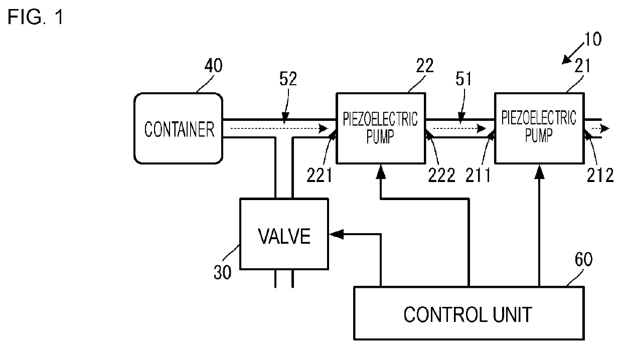
A fluid control device includes a piezoelectric pump, a piezoelectric pump, a valve, and a container. The piezoelectric pump and the piezoelectric pump repeat the operation and the stop in accordance with a drive control cycle. The valve starts a control to close at the start timing of one cycle of the drive control cycle and starts a control to open at the stop of the piezoelectric pump and the piezoelectric pump. The time from the start timing of one cycle of the drive control cycle to the time at which the piezoelectric pump on the upstream side pump reaches a normal operation drive voltage is longer than the time from the start timing to the time at which the piezoelectric pump on the downstream side reaches a normal operation drive voltage.
Description
[0001]This is a continuation of International Application No. PCT / JP2019 / 002922 filed on Jan. 29, 2019 which claims priority from Japanese Patent Application No. 2018-075104 filed on Apr. 10, 2018. The contents of these applications are incorporated herein by reference in their entireties.BACKGROUNDTechnical Field[0002]The present disclosure relates to a fluid control device that uses a piezoelectric pump to move fluids to a predetermined direction.[0003]Patent Document 1 describes a fluid control device including a piezoelectric pump and a driver circuit. The driver circuit is connected to the piezoelectric pump and supplies a drive voltage to the piezoelectric pump. The piezoelectric pump sucks fluids from a suction inlet and discharges from a discharge outlet in response to the drive voltage. This moves fluids in a predetermined direction.[0004]Patent Document 1: Japanese Patent No. 6160800 specificationBRIEF SUMMARY[0005]As a way to use a fluid control device, it is conceivable ...
Claims
Application Information
Patent Timeline
Application Date:The date an application was filed.
Publication Date:The date a patent or application was officially published.
First Publication Date:The earliest publication date of a patent with the same application number.
Issue Date:Publication date of the patent grant document.
PCT Entry Date:The Entry date of PCT National Phase.
Estimated Expiry Date:The statutory expiry date of a patent right according to the Patent Law, and it is the longest term of protection that the patent right can achieve without the termination of the patent right due to other reasons(Term extension factor has been taken into account ).
Invalid Date:Actual expiry date is based on effective date or publication date of legal transaction data of invalid patent.

