Fastening device for holding a sensor

a technology for fastening devices and sensors, applied in the field of sensors, can solve problems such as production stoppages, sensor disruptions, and preventing the sensor from operating correctly

Active Publication Date: 2022-07-19
PAYRAUD PIERRE
View PDF7 Cites 0 Cited by
  • Summary
  • Abstract
  • Description
  • Claims
  • Application Information

AI Technical Summary

Benefits of technology

[0016]A problem proposed by the present invention is to provide a fastening device for holding a sensor that allows any disruptions of the sensor caused by a polluting environment to be reduced and even avoided, without significantly increasing the footprint of the fastening device, which generally has limited available space in the environment.
[0017]At the same time, the aim of the present invention is to provide a fastening device for holding a sensor that allows more effective protection of the sensor in a polluting environment and also allows the operation of a sensor to be restored after it has been rendered inoperative by the polluting environment.

Problems solved by technology

The sensor can be disrupted by a polluting environment, for example, by projections of cutting oil, material swarf or filings that deposit onto the distal end of the sensor.
These deposits can prevent the sensor from operating correctly.
This therefore results in production stoppages that reduce productivity fairly significantly.
Introducing a stop by means of a radial flared portion, with which the detection face of the sensor would make contact, would interrupt (and even remove) this barrier and would thus degrade the desired protection of the sensor.
Furthermore, the cylindrical protective barrier does not fully protect the detection face of the sensor.

Method used


Image

  • Fastening device for holding a sensor
  • Fastening device for holding a sensor
  • Fastening device for holding a sensor

Examples


first embodiment

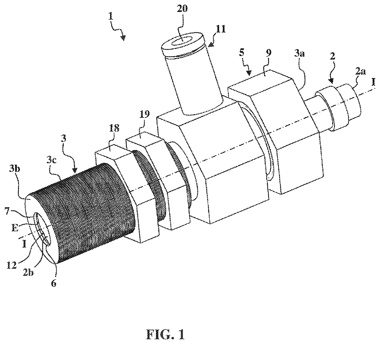
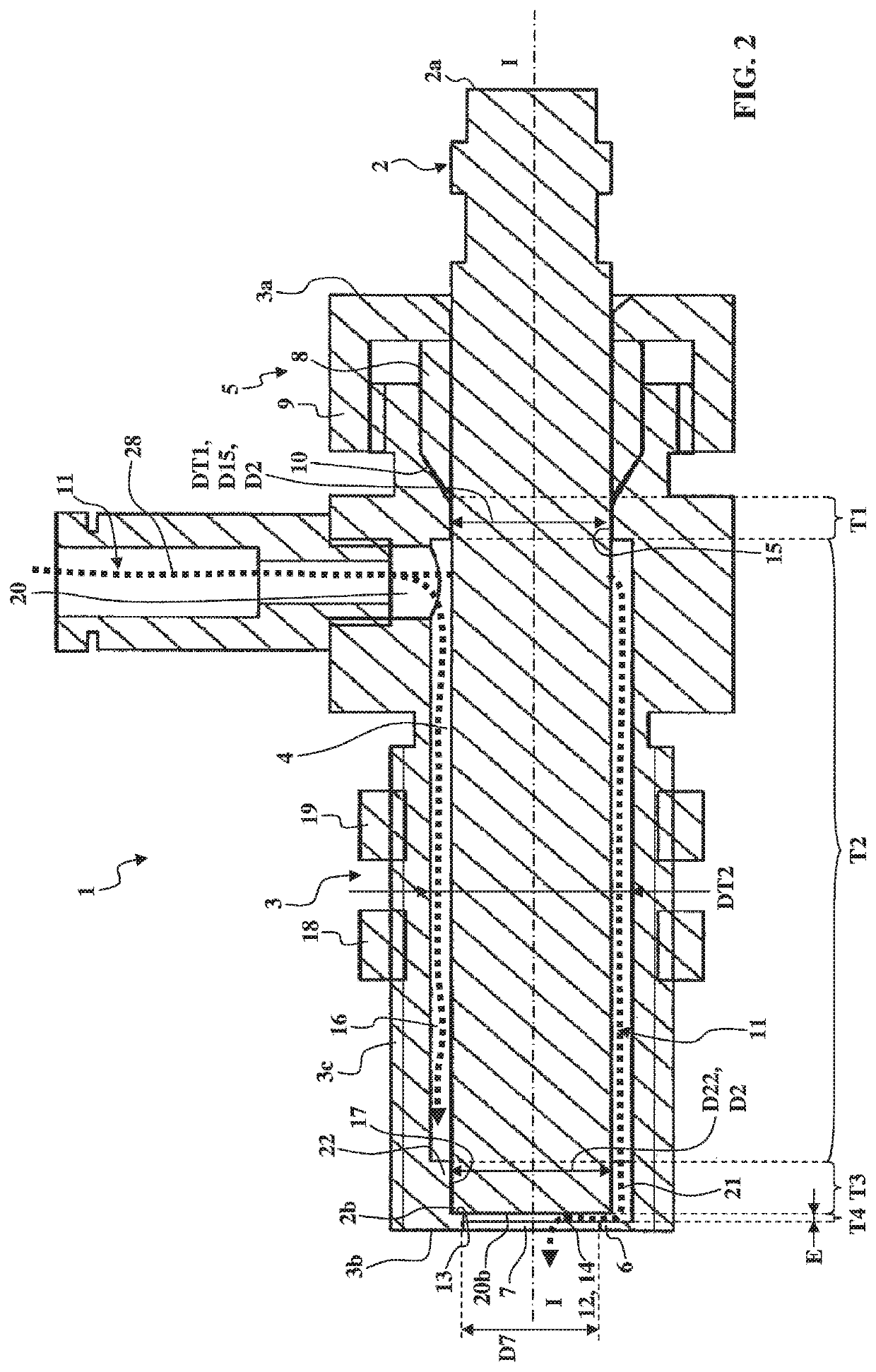
[0070]FIGS. 1 to 6 show a fastening device 1 according to the invention for holding a sensor 2. The sensor 2 has a cylindrical form limited by a proximal end 2a and a distal end 2b with a frontal end surface 20b.

[0071]The fastening device 1 comprises:[0072]a tubular body 3 extending along a median longitudinal axis I-I between a first end 3a and a second end 3b and comprising a longitudinal through passage 4 intended to receive said sensor 2;[0073]means 5 for axially immobilizing the sensor 2 in the longitudinal through passage 4.

[0074]The longitudinal axis I-I is median in that it is substantially located at the center of the longitudinal through passage 4.

[0075]The tubular body 3 comprises an external thread 3c so as to engage with a nut 18 and a lock nut 19 in order to be assembled through a wall of a machine tool or an automated line.

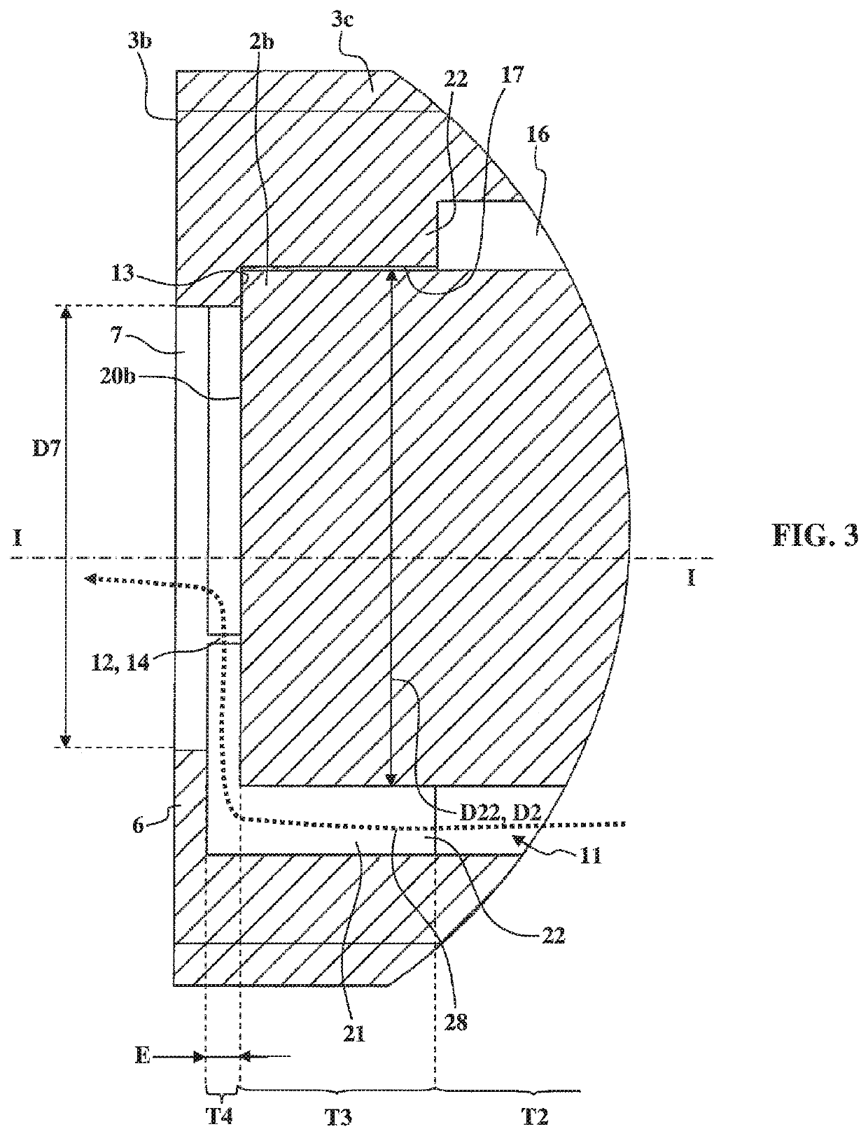
[0076]At the second end 3b of the tubular body 3, a flared portion 6 extends radially inwards (in other words by moving closer to the median longi...

second embodiment

[0107]In this second embodiment, a nut 25 engaging with the external thread 2c also can be used to limit the screwed penetration of the sensor 2 into the tubular body 3 in order to keep the distal end 2b of the sensor 2 at a predetermined longitudinal distance from said flared portion 6. The nut 25 thus can be used when the stop faces 13 define an excessively short minimum non-zero predetermined longitudinal distance from the flared portion 6 (or when it is preferable for a greater distance to be provided between the distal end 2b of the sensor 2 and the flared portion 6 than that which is provided by the stop faces 13).

[0108]As in the first embodiment, the second embodiment of a fastening device 1 comprises an external thread 3c of the tubular body 3 so as to engage with a nut 18 and a lock nut 19 so that it can be assembled through a wall of a machine tool or automated line.

[0109]The third embodiment of a fastening device 1 shown in FIGS. 8 and 9 is also very similar to the first ...

third embodiment

[0110]In the third embodiment, instead of an external thread 3c provided on the tubular body 3 in order for it to be fastened on a machine tool or automated line, the tubular body 3 comprises a radial flared portion 26, in which an oblong hole 27 is arranged that is intended to be traversed by one or more screws 30 intended to be screwed into the machine tool or automated line.

[0111]It must be noted that the tubular body 3 of the third embodiment of a fastening device 1 alternatively can comprise axial immobilization means 5 similar to those used in the first embodiment (with the conical ring 8, the nut 9 and the conical bearing surface 10) in order to receive sensors 2 without an external thread 2c on the external surface thereof.

[0112]The operation of the second and third embodiments of a fastening device 1 is very similar to that of the first embodiment.

[0113]One difference is that the penetration of the sensor 2 can be stopped before the distal end 2b comes into abutment against...


PUM


Abstract

A fastening device for holding a sensor has a cylindrical form limited by a proximal end and a distal end. The fastening device includes a tubular body extending along a median longitudinal axis (I-I) between a first end and a second end, and including a longitudinal through passage for receiving the sensor. At the second end of the tubular body there is a flared portion extending radially inwards and defining an orifice with a cross-section of smaller dimensions than the cross-section of the sensor. The fastening device also includes a device for axially immobilizing the sensor in the longitudinal through passage. The axial immobilization device is shaped so as to keep the distal end of the sensor at a longitudinal distance (E) from the flared portion. The fastening device is a device for bringing a fluid inside the tubular body and into the space between the flared portion and the distal end of the sensor.

Description

CROSS-REFERENCE TO RELATED APPLICATIONS[0001]This application claims the benefit of international application No. PCT / IB2017 / 055422, filed Sep. 8, 2017, which claims the benefit of French Patent Application No. FR16 58483, filed on Sep. 12, 2016.TECHNICAL FIELD OF THE INVENTION[0002]The present invention relates to the field of sensors and, more specifically, relates to a fastening device for holding a sensor.[0003]Proximity sensors are known that have a cylindrical form limited by a proximal end and a distal end. These sensors can be capacitive, inductive, optoelectronic or optical fiber sensors, for example, and most often have a circular cross-section. Such sensors are used, for example, in a machine tool or on an automated manufacturing line for detecting the presence of an object and / or for measuring the distance at which the object is located.[0004]In order to hold one of these sensors in a fixed position relative to their environment, a fastening device, which is marketed by ...

Claims


Application Information

Patent Timeline
Patent Type & Authority Patents(United States)
IPC IPC(8): G01D11/30B08B3/02
CPCG01D11/30B08B3/02G01D3/028G01D11/245
Inventor PAYRAUD, PIERRE
Owner PAYRAUD PIERRE
Why Eureka
Try Eureka