Dynamic fire suppression system and method i'hereof

a fire suppression system and dynamic technology, applied in the field of actuators, can solve the problems of general cost of design and installation, complex design and installation of engineered systems, and general limitation of engineered fire suppression systems to larger facilities, and achieve the effect of cost effectiv

Active Publication Date: 2022-08-09
USSC ACQUISITION CORP D B A UNITED SAFETY & SURVIVABILITY CORP
View PDF1 Cites 0 Cited by
  • Summary
  • Abstract
  • Description
  • Claims
  • Application Information

AI Technical Summary

Benefits of technology

[0014]One substantial advantage of the present invention, in particular is located in the actuation device or actuating portion of the fire extinguisher which provides a safety pin inserted into the valve, allowing for safe transport, installation, and servicing, but yet provides feedback to the control panel of any unit where the safety pin is not inserted into a keeper. More specifically, instead of monitoring the removal or presence of the safety pin in the lockout position, the actuator provides a separate area to place the safety pin for storing securely, and provides feedback to the control system that the safety pin is properly stored and therefore, the fire extinguisher is active. The safety pin must be removed for operation, and the system reports the operational condition of each fire extinguisher back to the control system. More specifically, the safety pin upon removal from the locking hole is reinserted into a separate opening, which actuates the communication to the control system regarding status. As such, proper installation of each fire extinguisher may easily and cost effectively be determined.
[0015]The present invention is directed generally to a pre-engineered fire suppression system configured to release pressurized material to extinguish fires, generally including a control panel, a sensor capable of detecting a fire condition and in communication with the control panel, at least one fire extinguishing unit in communication with the control panel and including an activation device coupled to a tank capable of holding the pressurized material and wherein the activation device includes a first triggering mechanism capable of being triggered by the control panel and a second manual triggering mechanism, and a lock pin status sensor in communication with the control panel.
[0016]The activation device may include a valve body portion having a lock pin receiving recess and an activation portion, having a lock pin retention mechanism. The lock pin retention mechanism may include the lock pin status sensor in communication with the control panel. The lock pin retention mechanism may include a magnet configured to magnetize a lock pin when the lock pin is received in the lock pin retention mechanism. The lock pin status sensor may be a reed switch, triggered when the lock pin is magnetized by the magnet. The magnet then not only secures the lock pin in the recess but the lock pin status sensor also communicates a ready and active signal upon stowing of the lock pin in the lock pin retention mechanism to the control panel. The lock pin status sensor communicates a fault signal to the control panel when no lock pin is stowed in the lock pin retention mechanism. The lock pin recess on the valve portion upon receiving a lock pin is configured to prevent releasing of the pressurized material from the tank.
[0017]The present invention may include a third release mechanism or even additional release mechanisms. An exemplary additional release mechanism is a glycerin bulb configured to shatter upon reaching a set temperature condition.
[0018]The actuation device may further include an activation portion and a valve portion and a lever mechanism extending between the activation portion and the valve portion and wherein the valve portion includes a valve body and a valve movable between an open position and a closed position relative to the valve body. The lever mechanism includes a valve lever coupled to an actuation lever. The valve lever is constrained to movement substantially within a plane by a slot in the valve body.
[0019]The valve is held in a closed position by a breakable pin held in compression between by the valve body. The breakable material may be formed of any material capable of providing the desired function, however in the illustrated figures it is a glass pin or a glass bulb without glycerin or a glass pin or bulb filled with glycerin. The breakable pin is held in compression between a threaded adjustment and the valve. The valve lever is coupled to the breakable pin, such as by the illustrated loop, wherein the valve lever includes an interlink hole and a lock pin hole between the interlink hole and the loop. The actuation lever includes an activation arm and a link arm and wherein the link arm includes a link slot and the valve lever is coupled to the link arm to allow the valve lever to have a limited amount of movement relative to the link arm on the actuation lever. The loop pivots on the breakable pin until the breakable pin breaks when the actuation lever exerts a force on the valve lever. The actuation lever is substantially constrained to planer movement by a slot in the activation portion.

Problems solved by technology

Engineered fire suppression systems are typically design specific or building specific and are generally expensive to design and install as they are customized for each location.
Stated another way, an engineered system is complex to design and install.
As such, engineered fire suppression systems are generally limited to larger facilities, or to fulfill specialized needs that cannot be addressed by pre-engineered systems.
These portable fire extinguishers are generally of limited use because they require personnel to be present at the location of the fire when it occurs, and to be ready, willing, able, and trained in the proper use to quickly put out a fire before it reaches a size that a portable handheld fire extinguisher would have little effect or the person activating it cannot get safely close enough to the source of the fire.
As such, handheld or portable fire extinguishers have limited utility in facilities, and larger facilities or specialized facilities need a full fire suppression system with more permanent and automatically actuating fire suppression systems, such as the above described engineered and pre-engineered fire suppression systems.
But water damage cannot always be tolerated such as in server rooms and certain types of facilities.
Thus sprinkler systems are sometimes ineffective, and they may be impractical where weight and space are limited, or where the water supply or volume of water is limited, or in unconditioned or refrigerated spaces.
While many pre-engineered fire suppression systems adopt the technology from handheld portable fire extinguishers into fixed bottled fire extinguishers that are part of a pre-engineered fires suppression system that is centrally actuated, there are issues that need to be addressed.
Some of these issues include how to disperse the agent in a desirable fashion, inability to manually actuate if they are connected to an automatic fire suppression system, and even more problematic, they can be subject to installation errors that make them inoperable or fail to discharge when desired, especially due to failure to remove the safety pin that prevents discharge during transportation and installation.
However, all of the aforementioned systems suffer from the disadvantage of only having one actuator, either automatic or temperature dependent, and are thus limited by criteria from which the valve can switch to the open state.
As such, they are not capable of being manually activated, except at the remote control panel or allowing for a combination of automatic control by a remote control panel in addition to temperature triggered, or especially not capable of all three methods of release or additional methods of release.
Another problem with these individual fire extinguishers being centrally actuated is monitoring the status of the fire extinguisher and more specifically if it was properly installed such that it is configured to operate.
However, many times installers forget to remove the safety pin or lockout device once installed and while the control panel for the fire suppression system shows that each fire extinguisher connected to the control panel in the pre-engineered system is connected properly, it failed to show if the safety pin was removed or the lock-out device was disabled to allow operation of the valve.
In certain circumstances, a person thinking that they are being helpful may put the pin back in the system causing it to not operate at a critical time and the operator would have no idea that device is locked out from operation.

Method used


Image

  • Dynamic fire suppression system and method i'hereof
  • Dynamic fire suppression system and method i'hereof
  • Dynamic fire suppression system and method i'hereof

Examples


Embodiment Construction

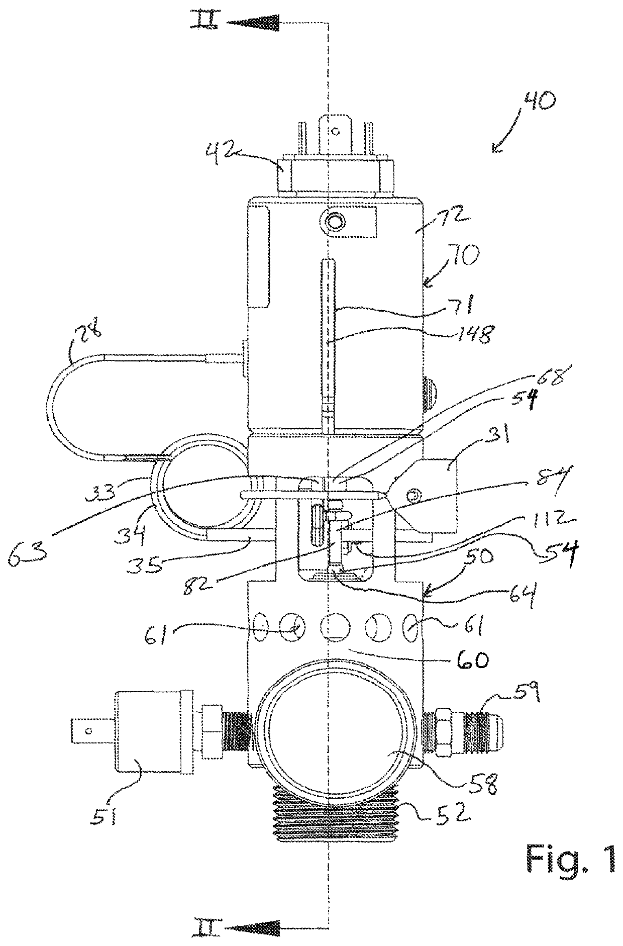
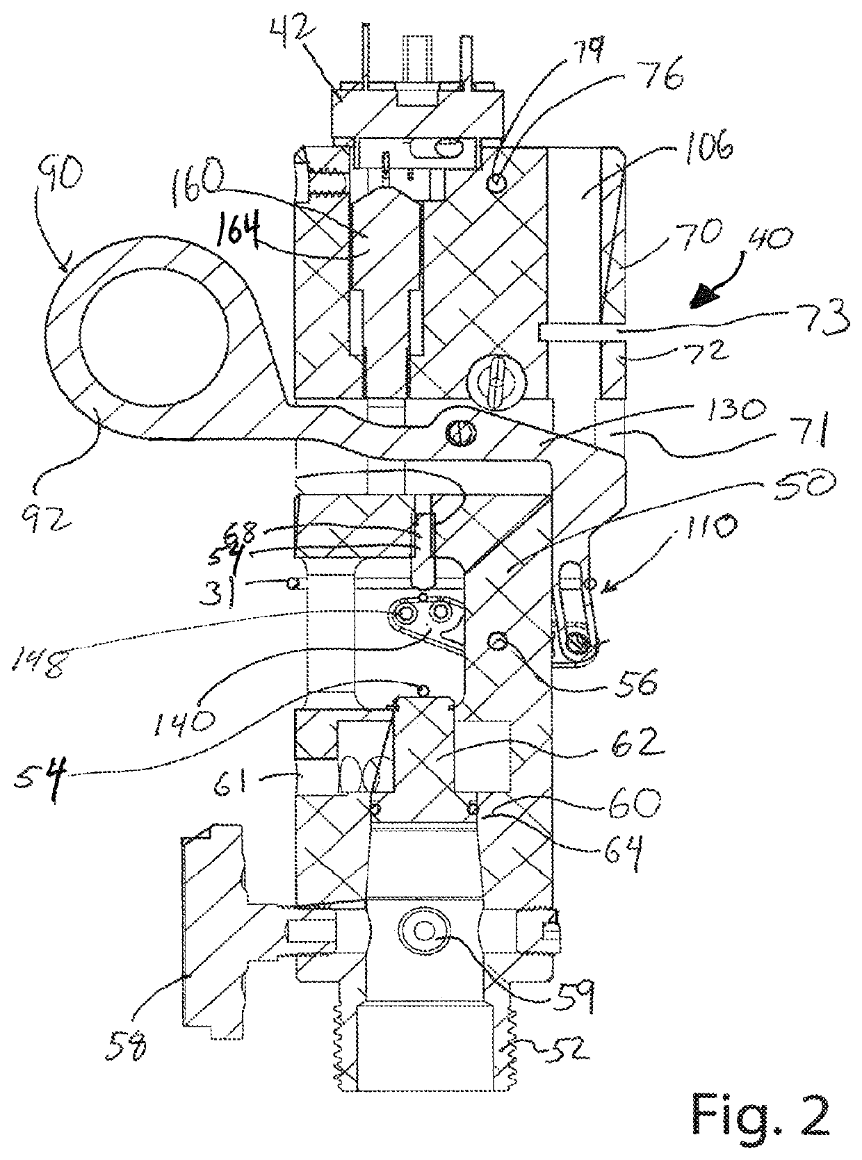
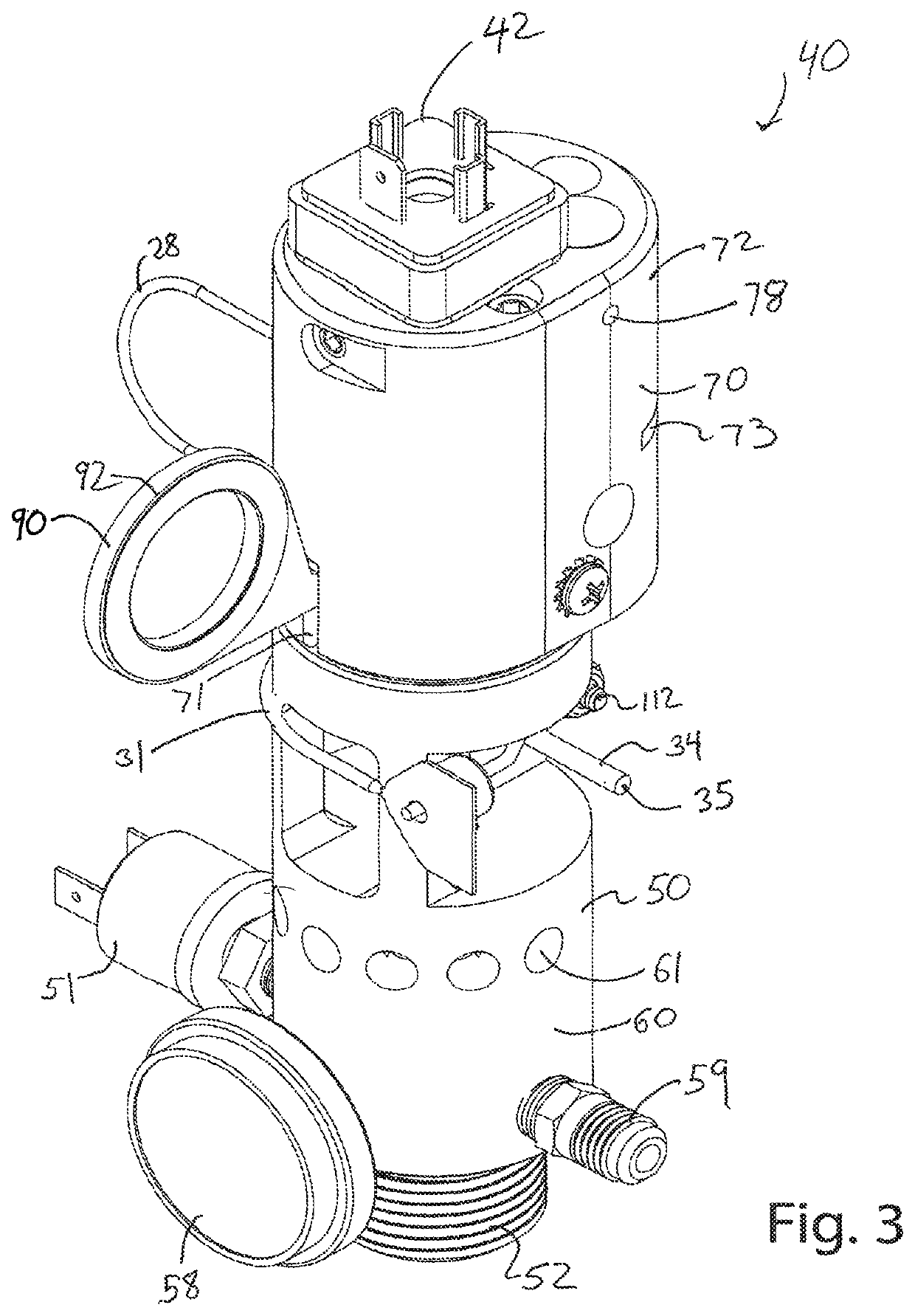
[0072]The invention provides a pre-engineered dynamic fire suppression system 20 that includes at least one fire extinguishing unit or device 30 in communication with a control panel 150 and at least one sensor 180 in communication with the control panel 18. Each fire extinguishing unit 30 includes an actuation device 40, having an actuation portion 90 and a valve portion 50, and a tank 32 capable of containing pressurized contents or material.

[0073]The tank 32 may be any type of tank commonly used to hold pressurized contents in the fire extinguishing industry. The size may vary, and commonly used in fire suppression systems are 25 cubic foot to 1500 cubic foot tanks, depending on numerous factors determined when designing the desired system 20. The contents of the tank 32 of the subject invention could be one or more fluids, dry chemicals, or the like. For a non-exhaustive list, these contents could include pressurized water, carbon dioxide, dry chemicals, ammonium phosphate, sodi...


PUM


Abstract

A fire suppression system having a first triggering mechanism capable of being remotely triggered in response to a fire condition and a second manual triggering mechanism. More particularly, the fire extinguisher includes a valve for a fire extinguisher capable of manual and automatic operation. The system further includes a mechanism to notify of inoperable local status. During automatic operation, the system can be being triggered by a control panel in electrical communication, such as in response to a signal from smoke detectors. This system may also be manually triggered or in response to a temperature threshold sensor or other sensors. The valve includes an actuator that provides a separate area to place a safety pin for storing securely, and which provides feedback to the control system that the safety pin is properly stored and therefore, the fire extinguisher is active.

Description

CROSS-REFERENCE TO RELATED APPLICATIONS[0001]This application claims the benefit of and priority to U.S. Provisional Patent Application Ser. No. 62 / 614,275 filed on Jan. 5, 2018, the entire disclosure of which is hereby incorporated by reference.BACKGROUND OF THE INVENTION1. Field of the Invention[0002]The invention relates generally to a fire suppression system, fire extinguishers for use in the fire suppression system, methods of releasing extinguisher fluid, and more particularly to actuators used for discharging fluid or gas in a fire extinguisher.2. Related Art[0003]Fire suppression systems are common in many facilities and many building codes and local ordinances require a fire suppression system. In addition, owners or tenants of every type of facility including industrial, commercial, and residential facilities and buildings find fire suppression systems desirable and useful, even if building codes or ordinances may not require a fire suppression system. For example, it may ...

Claims


Application Information

Patent Timeline
Patent Type & Authority Patents(United States)
IPC IPC(8): A62C13/64A62C37/42A62C37/46A62C37/40A62C35/02A62C37/50A62C35/13A62C13/00A62C37/36A62C37/11
CPCA62C13/64A62C13/003A62C35/023A62C35/13A62C37/04A62C37/11A62C37/40A62C37/42A62C37/46A62C37/50
Inventor DEYOUNG, PERRYFARRELL, JEREMIAH
Owner USSC ACQUISITION CORP D B A UNITED SAFETY & SURVIVABILITY CORP
Why Eureka
Try Eureka