Delivery device having a deflectable and peelable mapping guide sheath for his bundle pacing

a mapping guide and bundle technology, applied in the field of delivery devices, can solve the problems of increased risk of heart failure, increased risk of atrial fibrillation and overall mortality, and difficulty in pacing the bundle,

Active Publication Date: 2022-08-16
ST JUDE MEDICAL CARDILOGY DIV INC
View PDF13 Cites 1 Cited by
  • Summary
  • Abstract
  • Description
  • Claims
  • Application Information

AI Technical Summary

Problems solved by technology

While effective, this technique can cause abnormal electrical activation sequences resulting in mechanical ventricular dyssynchrony and an increased risk of heart failure, atrial fibrillation and overall mortality.
While the improved results obtainable with His pacing have been recognized, in practice His pacing is difficult to achieve because the bundle of His is very small and difficult to locate and access with the use of available or conventional lead delivery devices.
As a result of its small size and weak electrical signal, the bundle of His is extremely difficult to locate by a conventional lead delivery method.
Moreover, once the bundle of His has been located, it is difficult using a conventional lead delivery device to maintain the position of the lead while it is being affixed to the cardiac tissue.
The difficulties involved in locating the bundle of His and affixing a pacing lead thereto are reflected in the time it takes to implant the leads of an electrical stimulation device, such as a pacemaker.
To the contrary, the placement of a single lead for His pacing may take 30 minutes or more, frequently without success.
Another difficulty in implanting a His pacing lead concerns removal of the delivery device without disturbing the fixation of the pacing lead to the cardiac tissue.
This complicates the sheath removal process and becomes more difficult to do as the partially retracted delivery sheath makes accessing the pacing lead difficult.

Method used


Image

  • Delivery device having a deflectable and peelable mapping guide sheath for his bundle pacing
  • Delivery device having a deflectable and peelable mapping guide sheath for his bundle pacing
  • Delivery device having a deflectable and peelable mapping guide sheath for his bundle pacing

Examples


Embodiment Construction

[0038]As used herein, the terms “proximal” and “distal,” when used in reference to a delivery device, are to be taken as relative to a user of the delivery device. “Proximal” is to be understood as relatively close to the user and “distal” is to be understood as relatively far away from the user. As used herein, the terms “substantially,”“generally,” and “about” are intended to mean that slight deviations from absolute are included within the scope of the term so modified.

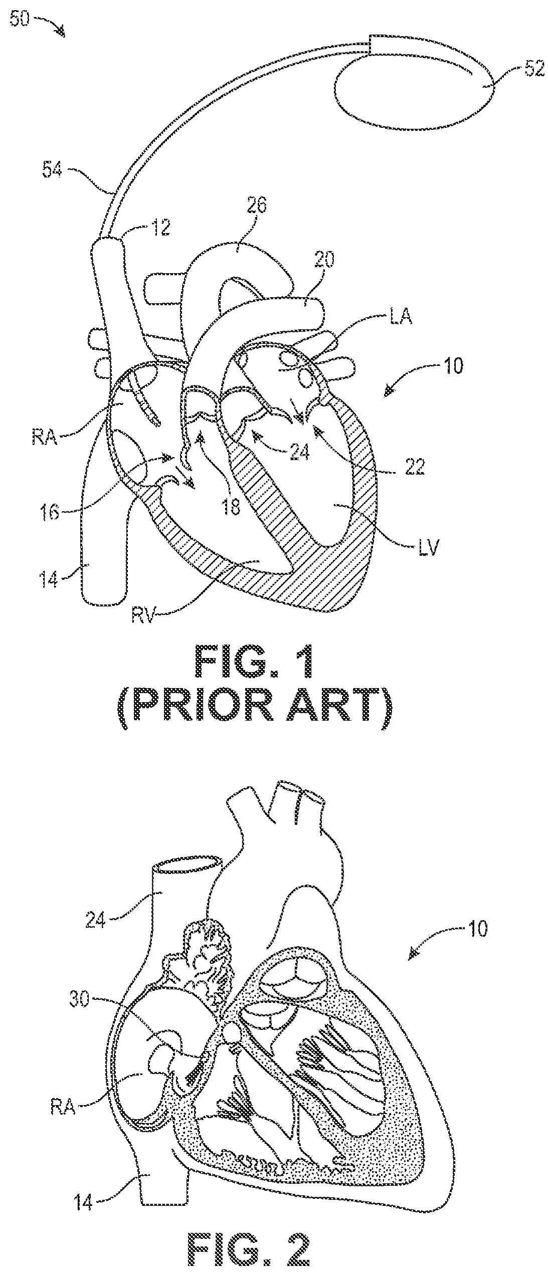
[0039]FIG. 1 is a highly schematic cutaway view of heart 10 illustrating the right atrium RA, the right ventricle RV, the left atrium LA, and the left ventricle LV. During normal operation of heart 10, deoxygenated blood from the body is returned to the right atrium RA from the superior vena cava 12 and inferior vena cava 14. The right atrium pumps the blood through the atrioventricular or tricuspid valve 16 to the right ventricle RV, which then pumps the blood through the pulmonary valve 18 and the pulmonary arter...


PUM


Abstract

A delivery device for delivering a pacing lead to the His bundle of a patient's heart includes an elongated sheath having a distal end, and a plurality of mapping electrodes positioned at the distal end. The distal end of the sheath may have a distal end face, and the mapping electrodes may include two electrodes that diametrically oppose one another at a position exposed on or spaced from the distal end face. The sheath includes a plurality of flexible sections spaced apart from one another, and a pull wire that causes the sheath to deflect from a substantially straight configuration to a dual hinged curved configuration that maneuvers and positions the electrodes in the vicinity of the bundle of His. The sheath may include a PTFE liner having axially oriented, platelet-like fibril features that enable the sheath to be split along its length from a proximal end to the distal end.

Description

[0001]The present disclosure relates to cardiac resynchronization therapy (CRT), and more particularly to a delivery device comprising a deflectable and peelable mapping guide sheath for locating the bundle of His and guiding an electrode lead thereto. Still more particularly, the present invention relates to a deflectable and peelable mapping guide sheath that is readily removable from the patient.BACKGROUND OF THE INVENTION[0002]Cardiac rhythm management systems are useful for electrically stimulating a patient's heart to treat various cardiac arrhythmias. The current standard of care is to pace the right ventricle by myocardial stimulation. In this technique, pacemaker leads are placed at the apex of the right ventricle and at the AV node, the coronary sinus or the left ventricle, and a pacemaker sends electrical pulses to these areas of the heart. While effective, this technique can cause abnormal electrical activation sequences resulting in mechanical ventricular dyssynchrony a...

Claims


Application Information

Patent Timeline
Patent Type & Authority Patents(United States)
IPC IPC(8): A61N1/05A61M25/06A61M25/01
CPCA61N1/059A61M25/0668A61N1/056A61M25/0108A61M2025/0681
Inventor GUO, XIAOPINGSTOERMER, ERICH W.
Owner ST JUDE MEDICAL CARDILOGY DIV INC
Why Eureka
Try Eureka