Apparatus and methods for delivery of prosthetic heart valves

a heart valve and appendix technology, applied in the field of appendix and methods for the delivery of prosthetic heart valves, can solve the problems of acute aortic insufficiency, damage to the mitral valve, and associated risks of traditional av loops, and achieve the effect of reducing the force applied

Active Publication Date: 2022-09-13
TENDYNE HLDG
View PDF10 Cites 0 Cited by
  • Summary
  • Abstract
  • Description
  • Claims
  • Application Information

AI Technical Summary

Benefits of technology

[0006]Apparatus and methods are described herein for use in in establishing an improved AV loop with the use of a pulley / snare device at the base of a ventricle of a heart. In some methods described herein, a pulley / snare device is established to create a path with inherent concentricity to the aortic and mitral valves, allowing the valves to function normally during an interventional procedure in the heart, without impeding the motion of any leaflets. The pulley / snare device described herein advantageously minimizes the forces applied on the valves or associated cardiac tissue to “make the turn” from the aortic valve to the mitral valve.

Problems solved by technology

Valvular heart disease, and specifically, aortic, and mitral valve disease is a significant health issue in the United States (US); annually approximately 90,000 valve replacements are conducted in the US.
A traditional AV loop can have associated risks.
Among these risks are possible damage to the aortic valve, damage to the mitral valve, acute aortic insufficiency, and acute mitral insufficiency.
The pressure and the relative movement of the guidewire or catheter against the aortic and / or mitral valves can have a “cheese cutter” effect and leave permanent damage to the valves.
Also, the pinch point created by the AV loop can restrict the aortic and / or mitral valve leaflets, causing acute insufficiency.

Method used


Image

  • Apparatus and methods for delivery of prosthetic heart valves
  • Apparatus and methods for delivery of prosthetic heart valves
  • Apparatus and methods for delivery of prosthetic heart valves

Examples


Embodiment Construction

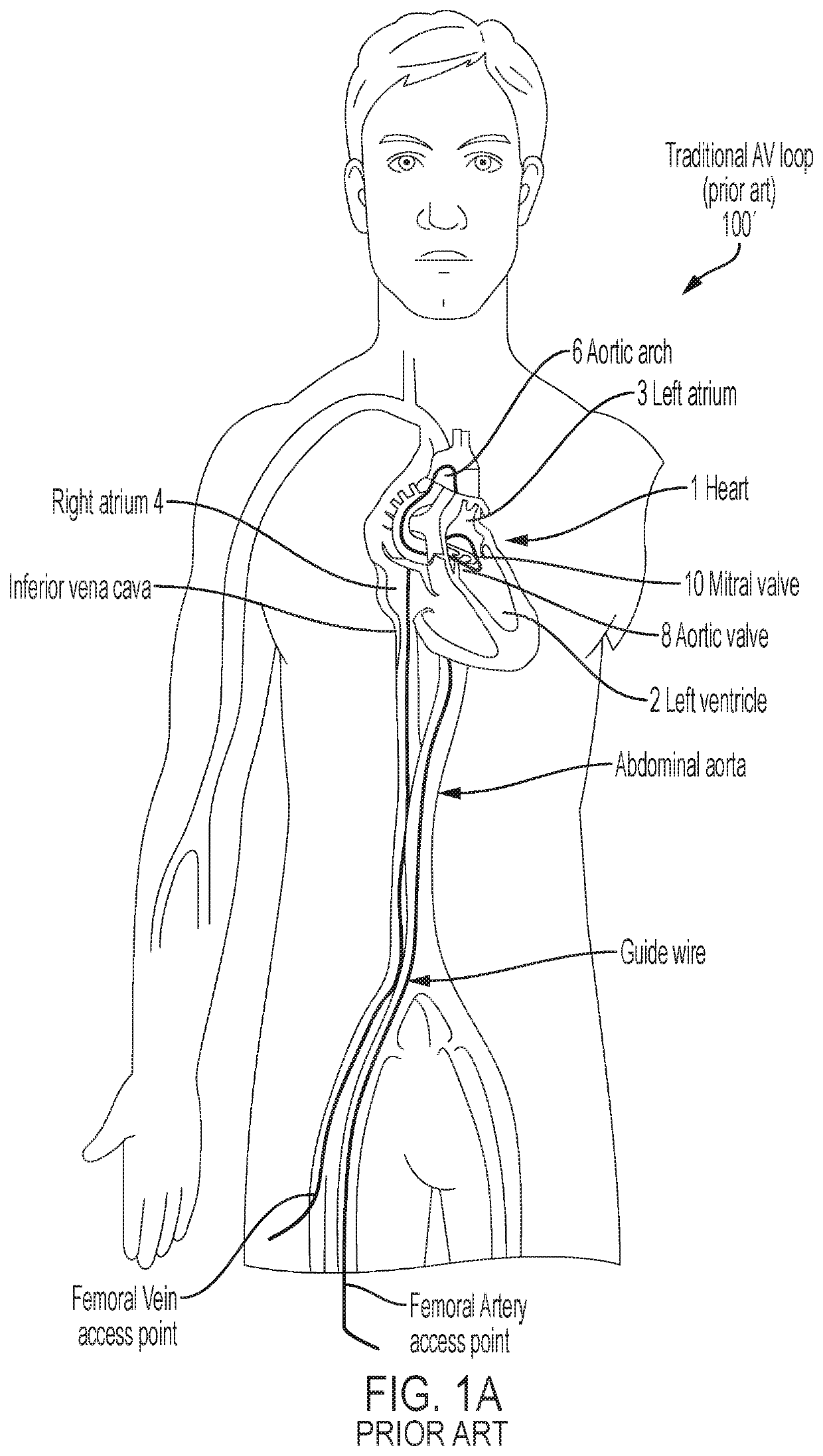
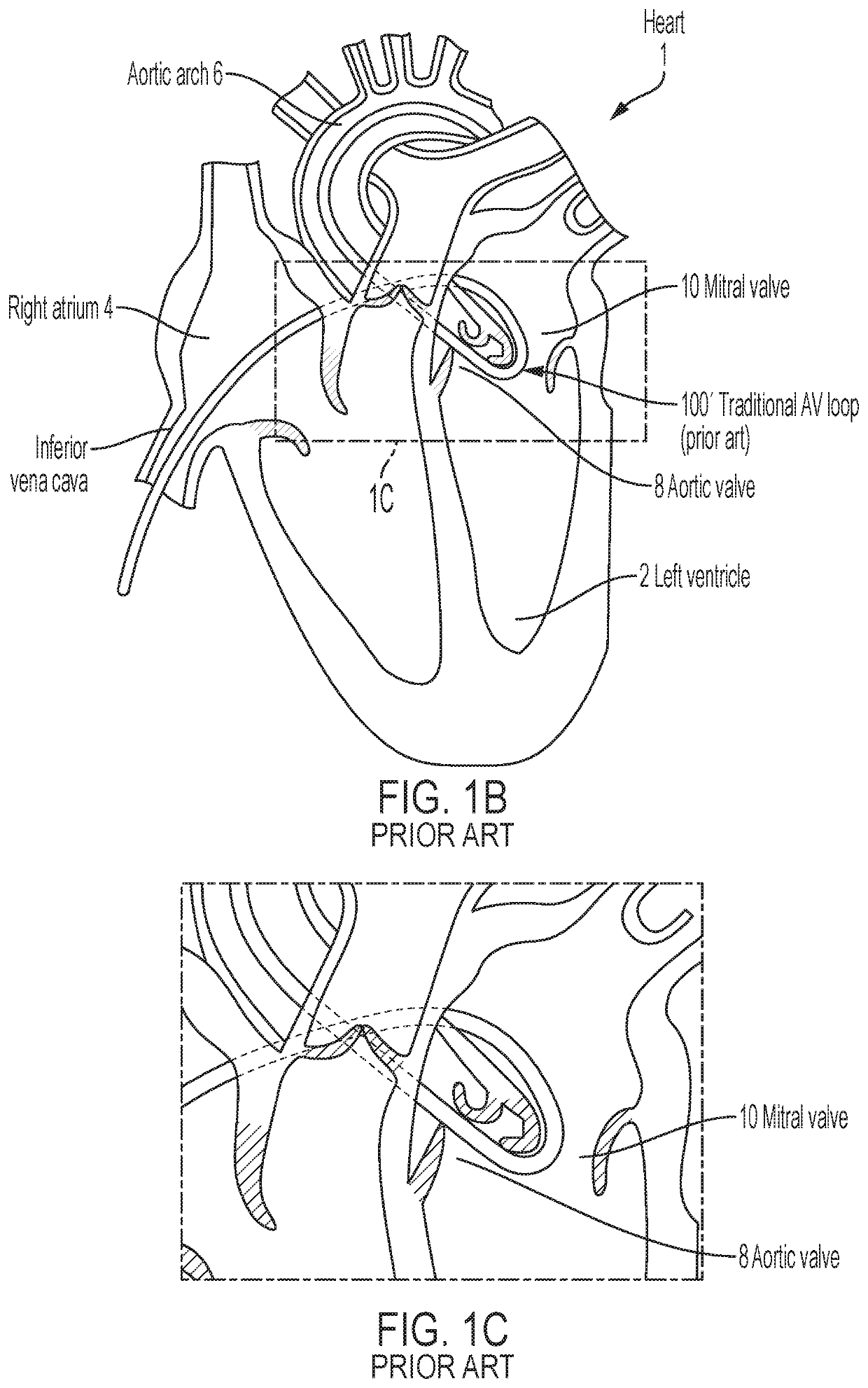
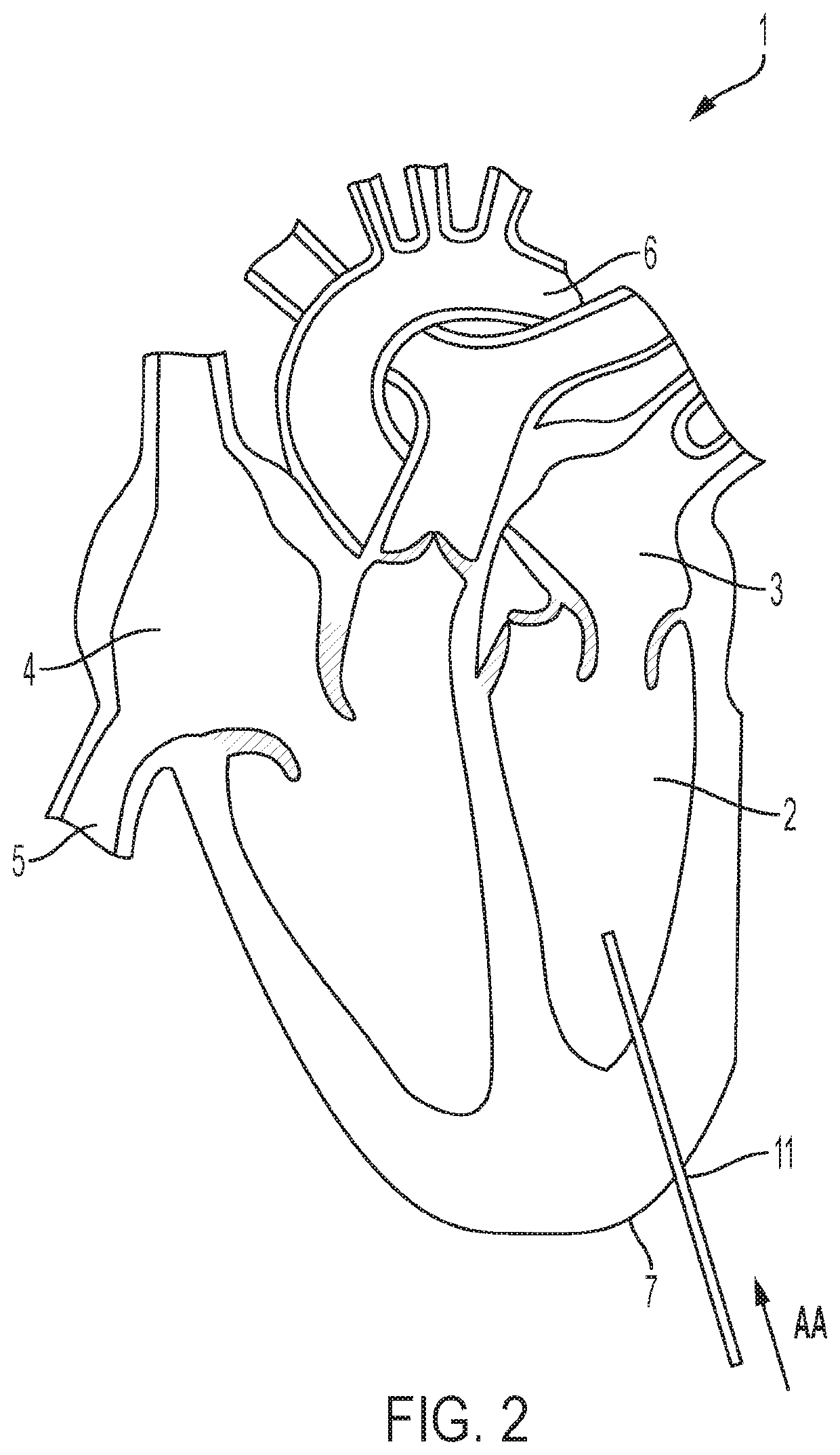
[0031]Apparatus and methods are described herein for use in establishing an improved AV loop with the use of a pulley / snare device at the base of a ventricle of a heart. As shown in FIGS. 1A and 1B, the current approach to establish a conventional arteriovenous (AV) loop 100′ involves drawing a guidewire against, and across, native cardiac tissue, such as the tissue associated with the native mitral valve and / or the native aortic valve. However, the forces exerted on the cardiac tissue supporting the conventional AV loop during establishment and use of the AV loop can be detrimental to the functioning of the aortic and the mitral valves and to cardiac health. According to the methods disclosed herein, the pulley / snare device established at the base of a ventricle of the heart creates a path with inherent concentricity to the aortic and mitral valve, allowing the valves to function normally without impeding the motion of any leaflets, as well as removing any force applied on the valv...


PUM


Abstract

Apparatus and methods are described herein for use in in establishing an improved AV loop with the use of a pulley / snare device at the base of a ventricle of a heart. In some methods described herein, a pulley / snare device is established to create a path with inherent concentricity to the aortic and mitral valves, allowing the valves to function normally during an interventional procedure in the heart, without impeding the motion of any leaflets. The pulley / snare device described herein minimizes the forces that are applied on the valves or associated cardiac tissue to “make the turn” from the aortic valve to the mitral valve.

Description

CROSS-REFERENCE TO RELATED APPLICATIONS[0001]This application claims the benefit of the filing date of U.S. Provisional Patent Application No. 62 / 882,178 filed Aug. 2, 2019, the disclosure of which is hereby incorporated herein by reference.BACKGROUND OF THE INVENTION[0002]Embodiments are described herein that relate to devices and methods for use in the implementation of an improved arteriovenous loop for various different interventional procedures including, for example, the delivery of one or more prosthetic heart valves.[0003]Prosthetic heart valves are used to replace native heart valves that may be damaged or diseased causing heart dysfunction. In vertebrate animals, the heart is a hollow muscular organ having four pumping chambers: the left and right atria and the left and right ventricles, each provided with its own one-way valve. The natural heart valves are identified as the aortic, mitral (or bicuspid), tricuspid, and pulmonary valves. Prosthetic heart valves can be used ...

Claims


Application Information

Patent Timeline
Patent Type & Authority Patents(United States)
IPC IPC(8): A61F2/24A61M25/09A61M25/10A61B17/34A61B17/04
CPCA61F2/2439A61B17/3468A61F2/2418A61F2/2433A61M25/09A61M25/1002A61B2017/0404A61F2220/0008A61F2220/0016A61F2/2412A61B2017/00358A61B2017/00247A61B17/3478A61F2/2427
Inventor VIDLUND, ZACHARY R.
Owner TENDYNE HLDG
Why Eureka
Try Eureka