
Surface cleaning apparatus with removable air treatment member assembly

a technology of air treatment member and surface cleaning apparatus, which is applied in the direction of suction handle, suction cleaner, domestic application, etc., can solve the problems of reducing cleaning efficiency, increasing back pressure, and reducing the air flow velocity at the dirty air inl

Active Publication Date: 2022-09-20
OMACHRON INTPROP
View PDF375 Cites 0 Cited by
  • Summary
  • Abstract
  • Description
  • Claims
  • Application Information

AI Technical Summary

Benefits of technology

This configuration enhances the performance of the surface cleaning apparatus by reducing wear on interfacing materials, preventing misalignment, and improving cleaning efficiency through reduced back pressure and increased air flow velocity, while also making the device more ergonomic and easier to handle.

Problems solved by technology

The directness and length of an air flow passage are important features of any surface cleaning apparatus, since an increase in the length of an air flow path through a surface cleaning apparatus and changes in air flow direction through an air flow path may result in an increase in back pressure and a reduction in air flow velocity at the dirty air inlet, which may result in a reduction in cleaning efficiency.
Sliding of materials against one another may be particularly damaging when the materials are air flow sealing materials, such as a gasket.

Method used


Image

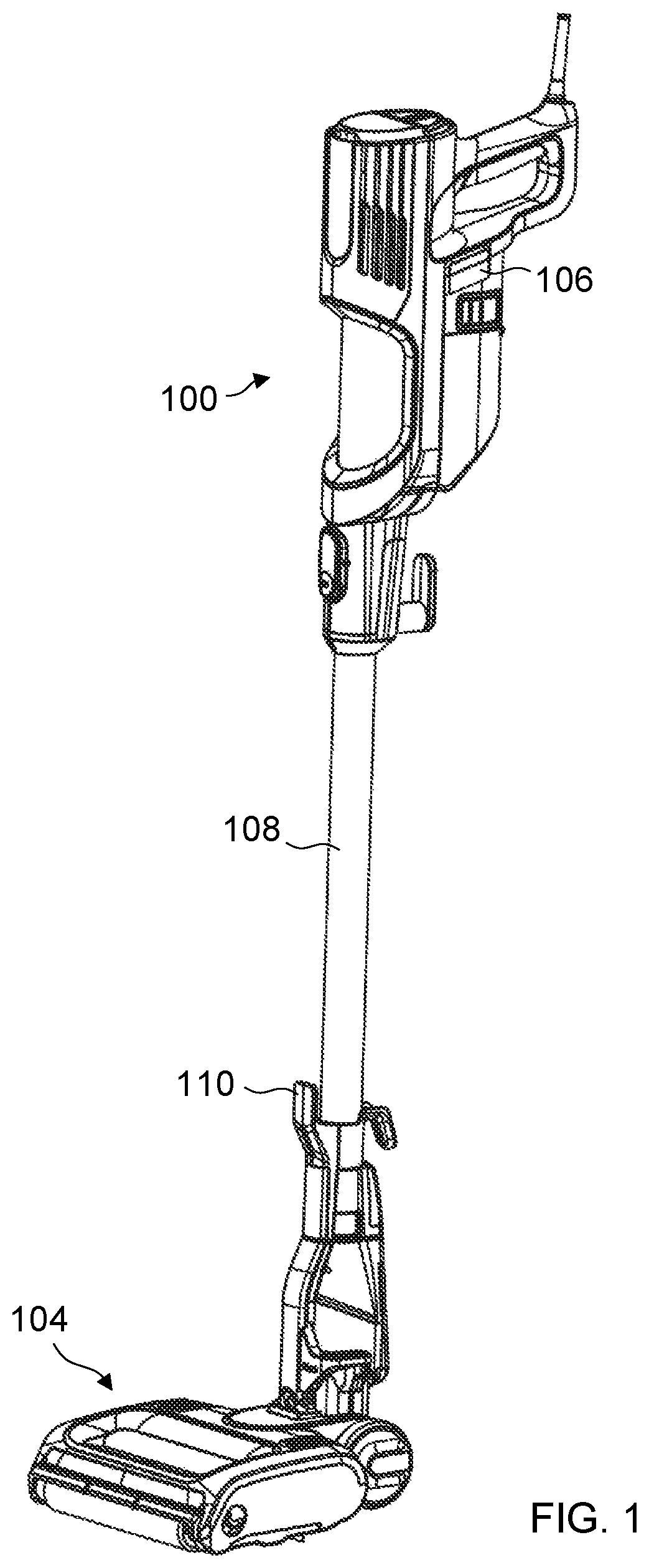
  • Surface cleaning apparatus with removable air treatment member assembly
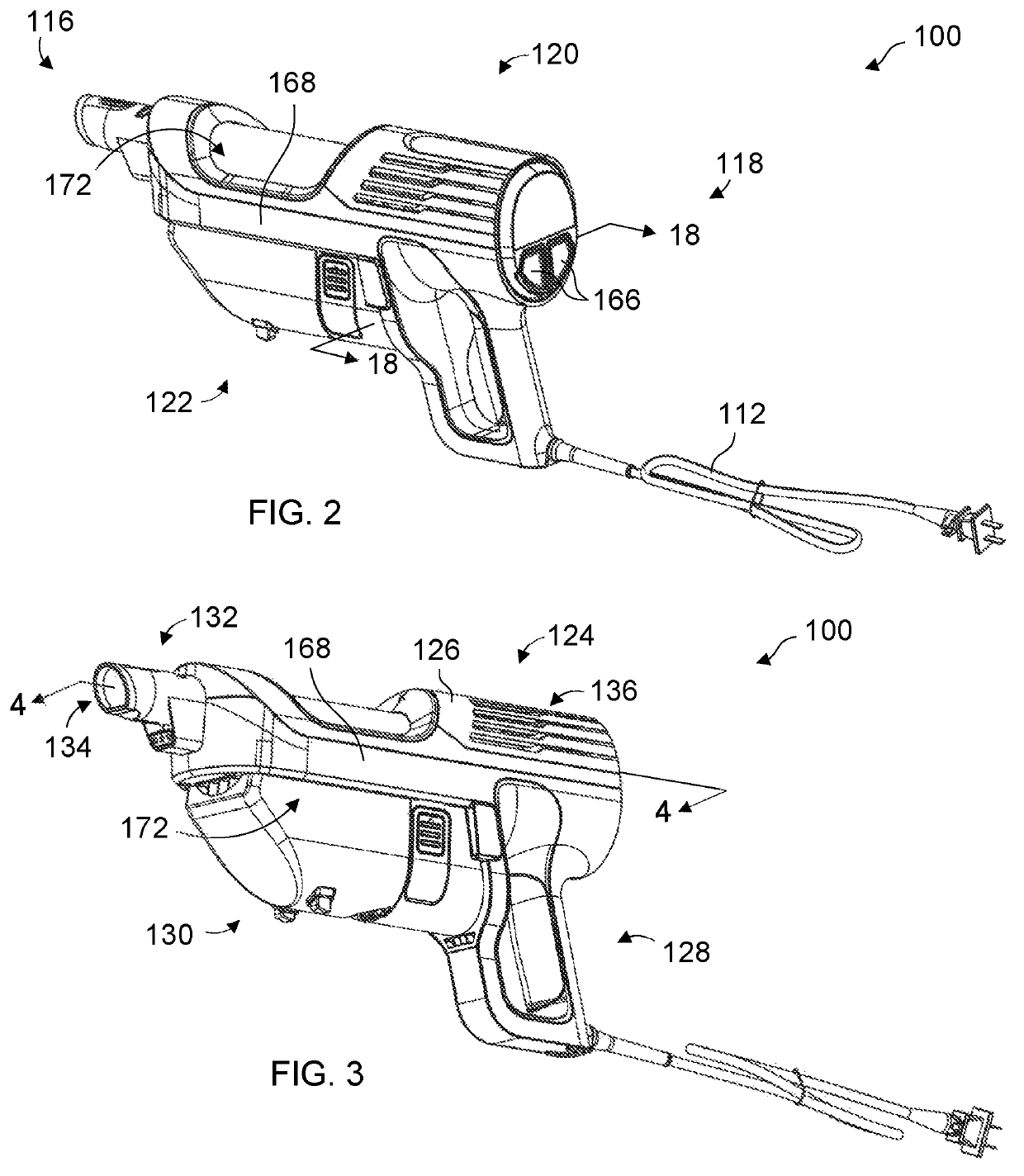
  • Surface cleaning apparatus with removable air treatment member assembly
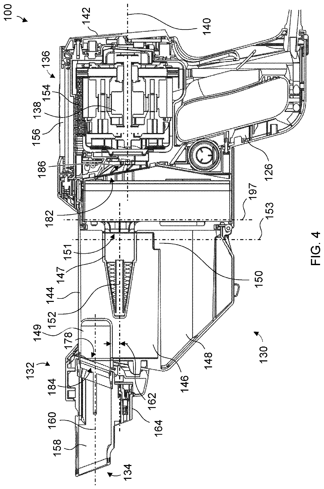
  • Surface cleaning apparatus with removable air treatment member assembly

Examples


Embodiment Construction

[0179]Various apparatuses, methods and compositions are described below to provide an example of an embodiment of each claimed invention. No embodiment described below limits any claimed invention and any claimed invention may cover apparatuses and methods that differ from those described below. The claimed inventions are not limited to apparatuses, methods and compositions having all of the features of any one apparatus, method or composition described below or to features common to multiple or all of the apparatuses, methods or compositions described below. It is possible that an apparatus, method or composition described below is not an embodiment of any claimed invention. Any invention disclosed in an apparatus, method or composition described below that is not claimed in this document may be the subject matter of another protective instrument, for example, a continuing patent application, and the applicant(s), inventor(s) and / or owner(s) do not intend to abandon, disclaim, or d...


PUM


Abstract

A hand vacuum includes a nozzle portion at a front end of the hand vacuum having a dirty air inlet. An air flow passage extends from the dirty air inlet to a clean air outlet in a main body rearward of the nozzle portion. The main body houses a suction motor in the air flow passage. First and second laterally spaced apart opposed arm members extend generally axially between the nozzle portion and the main body, and a volume is positioned between the nozzle portion, the main body and the opposed arm members. An air treatment member assembly comprising an air treatment member is removably downwardly from a position within the volume.

Description

FIELD[0001]This disclosure relates generally to surface cleaning apparatus, and in particular to a surface cleaning apparatus having a removable air treatment member assembly.INTRODUCTION[0002]The following is not an admission that anything discussed below is part of the prior art or part of the common general knowledge of a person skilled in the art.[0003]Various types of surface cleaning apparatus are known, including upright surface cleaning apparatus, canister surface cleaning apparatus, stick surface cleaning apparatus, central vacuum systems, and hand carriable surface cleaning apparatus such as hand vacuums. Further, various designs for cyclonic hand vacuum cleaners are known in the art.SUMMARY[0004]The following introduction is provided to introduce the reader to the more detailed discussion to follow. The introduction is not intended to limit or define any claimed or as yet unclaimed invention. One or more inventions may reside in any combination or sub-combination of the e...

Claims


Application Information

Patent Timeline
Patent Type & Authority Patents(United States)
IPC IPC(8): A47L9/16A47L9/32
CPCA47L9/1675A47L9/322A47L9/122A47L9/1691A47L9/165
Inventor CONRAD, WAYNE ERNEST
Owner OMACHRON INTPROP
Learn More