Tire pattern structure

a technology of pattern structure and tire, which is applied in the direction of special tyres, off-road vehicle tyres, vehicle components, etc., can solve the problems of affecting the durability of the tire pattern, reducing the ability of the tire to move forward, and affecting the performance of the tire, so as to facilitate the removal of extra mud or water, improve the ability of moving forward, and increase the quantity of mud carried by the tire in a u-turn

Active Publication Date: 2022-09-20
CHENG SHIN RUBBER
View PDF3 Cites 0 Cited by
  • Summary
  • Abstract
  • Description
  • Claims
  • Application Information

AI Technical Summary

Benefits of technology

[0006]In the aforementioned structures, a special design of the tire pattern is provided for the use on motor vehicles driving on off-roads, and the design of the tire pattern provides larger mud removing channels to prevent the mud from being clogged, but the comfortability of driving will be dropped due to a lower land ratio. Furthermore, the pattern blocks may be deformed too much while the motor vehicle is being driven or braked since the rigidity of a single pattern block is insufficient. Therefore, the durability of the tire pattern will be affected adversely, and the tire performance will be dropped significantly. To overcome the durability of the tire pattern and the comfortability of driving on off-roads, it is necessary to design a novel tire pattern that takes every function into consideration to improve the performance of the pattern structure.
[0009]The ranges of these angles provide the best effect. If the angle is too small, the forward resistance will be large, particularly for the sandy land. If the angle is too large, then the effect of removing mud will be reduced.
[0011]Compared with the prior art, the present invention provides a tire pattern structure with a spoon-shaped block warped in a direction from the handle block towards the center of the tread, so that the direction of removing mud is always in a backward direction, so as to improve the ability of moving forward on a muddy land. The spoon-shaped pattern blocks are interlaced in a V-shape to facilitate extra mud or water to be removed from both sides. The quantity of mud carried by the tire in a U-turn is increased, so that the tire can be moved easily on the sandy land. In addition, the water removing function of the tire is enhanced, so that a motor vehicle can reduce the forward resistance when wading in water.
[0012]Another objective of the present invention is to provide a tire pattern structure with a slot between the tread patterns to adjust the elasticity of the pattern block and improve the rigidity of the pattern block.
[0013]A further objective of the present invention is to provide a tire pattern structure having shoulders disposed on both sides and bent to the sidewall pattern, and the design with a vertical step difference of the block of the sidewall pattern and a sideway interlace and mapping can improve the climbing ability of the tire.
[0014]Another objective of the present invention is to provide a tire pattern structure with a bridge between the spoon-shaped pattern blocks for forming the connection between the groove, and such arrangement not just strengthens the rigidity of the block only, but also removes the mud in a specific direction to reduce the uncertainty of splashing.

Problems solved by technology

Furthermore, the pattern blocks may be deformed too much while the motor vehicle is being driven or braked since the rigidity of a single pattern block is insufficient.
Therefore, the durability of the tire pattern will be affected adversely, and the tire performance will be dropped significantly.
If the angle is too small, the forward resistance will be large, particularly for the sandy land.

Method used


Image

  • Tire pattern structure
  • Tire pattern structure
  • Tire pattern structure

Examples


Embodiment Construction

[0020]The technical characteristics, contents, advantages and effects of the present invention will be apparent with the detailed description of a preferred embodiment accompanied with related drawings as follows. The drawings are provided for the illustration, and same numerals are used to represent respective elements in the preferred embodiments. It is intended that the embodiments and drawings disclosed herein are to be considered illustrative rather than restrictive. Same numerals are used for representing same respective elements in the drawings.

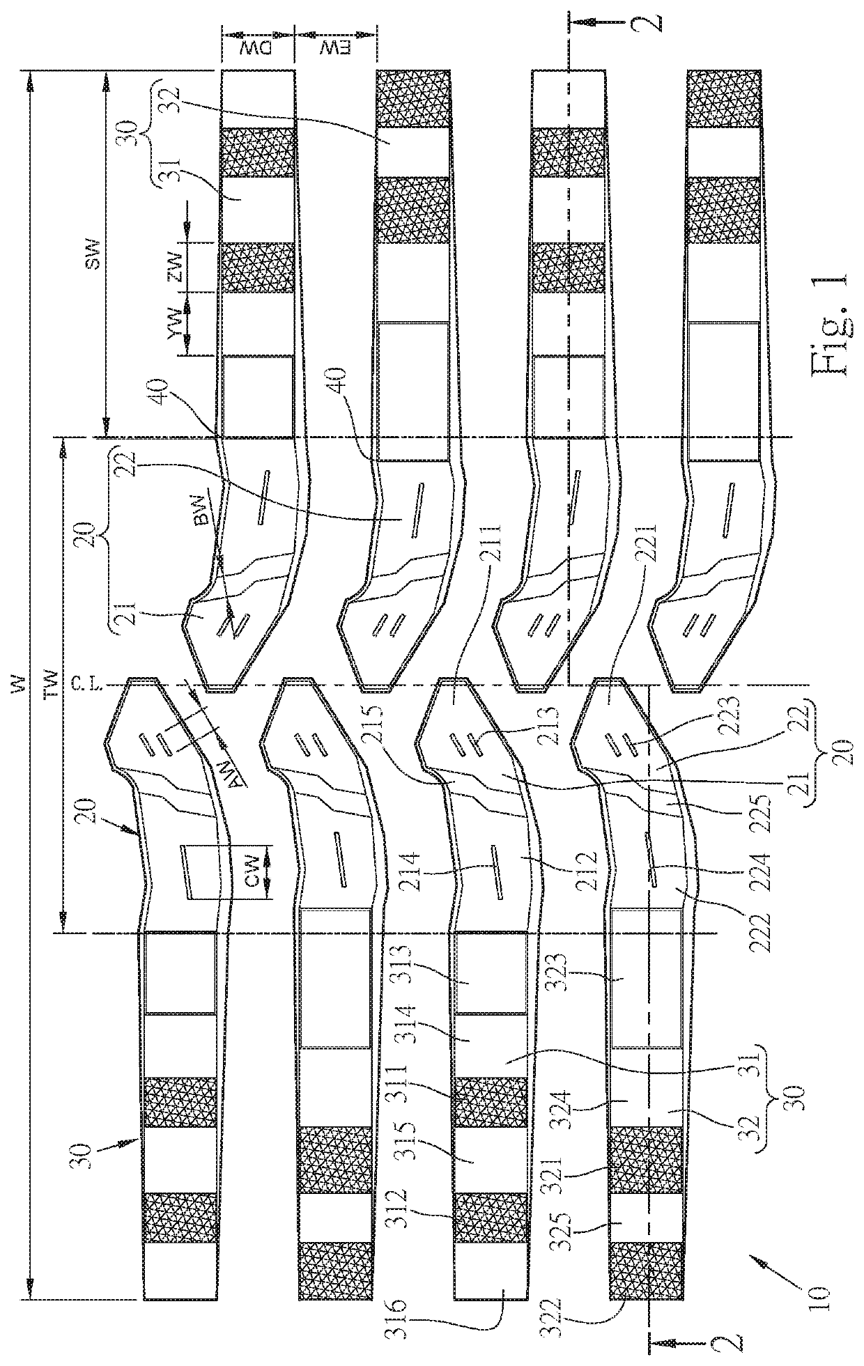
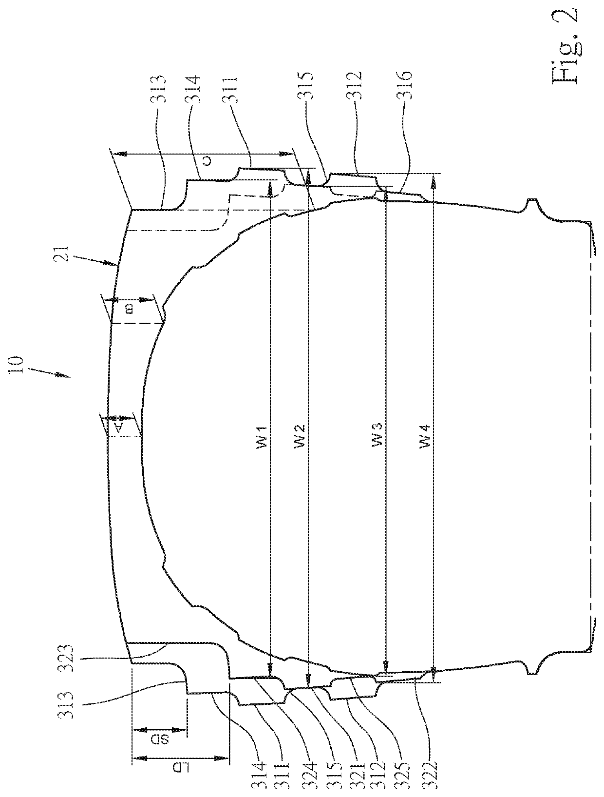
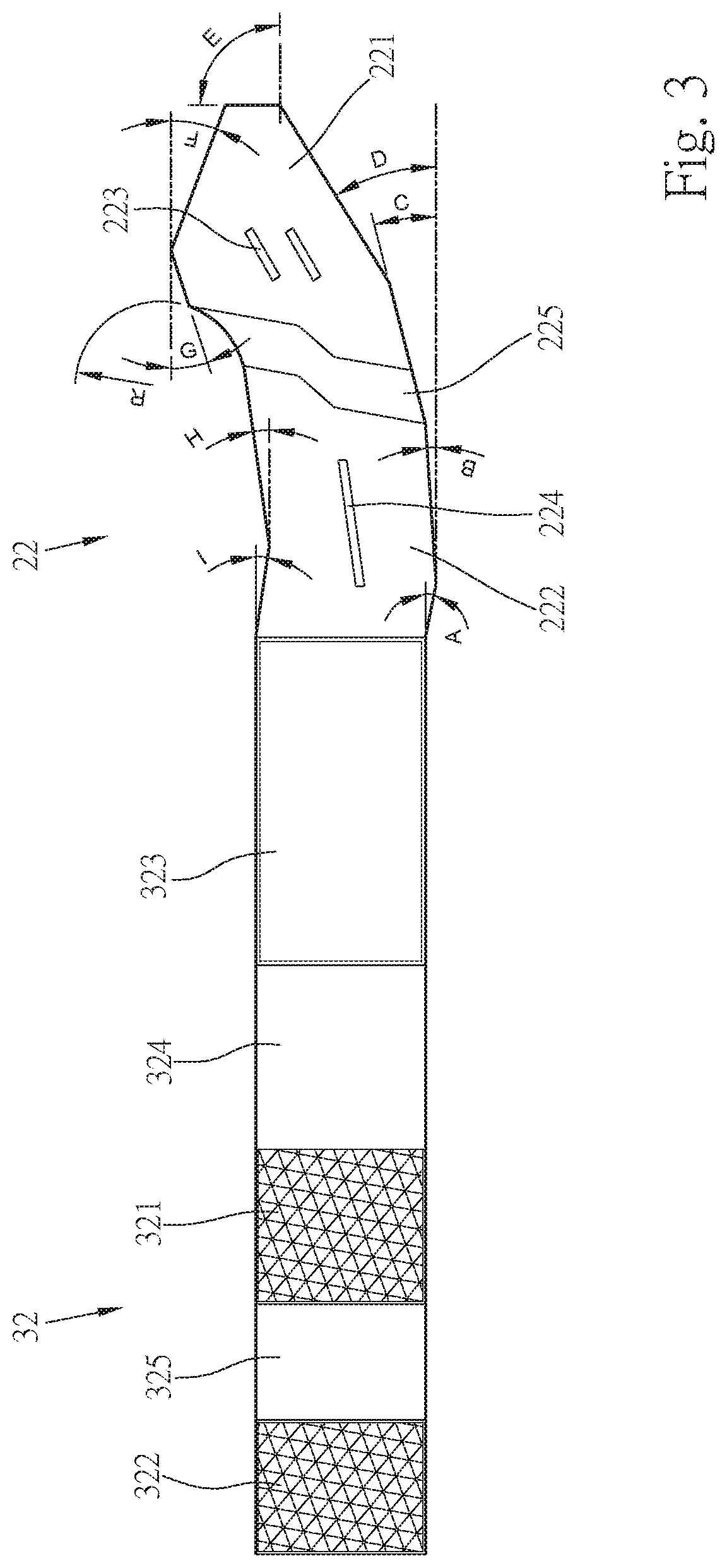
[0021]With reference to FIGS. 1 to 3 for a tire pattern structure of the present invention, the tire pattern (10) comprises a tread pattern (20) and a sidewall pattern (30), and the tire pattern (10) is formed by arranging and combining a plurality of uniformly distributed patterns along the circumferential direction of the tire, characterized in that the tread pattern (20) is formed by an upper spoon-shaped pattern (21) and a lower sp...


PUM


Abstract

A tire pattern structure including a tread pattern and a sidewall pattern is formed by uniformly distributed patterns in the circumferential direction of a tire. The tread pattern is formed by two long spoon-shaped pattern blocks symmetrical with respect to the center of the tire tread and the axial direction of the tire. A spoon-shaped pattern block group is across the center of the tire tread and each interlaced and mapped sideway along the center of the tire tread formed by upper and lower long spoon-shaped pattern block groups. The two spoon-shaped patterns are coupled from a head block to a handle block and bent at the tire shoulder to couple the sidewall pattern formed by the upper and lower sidewall pattern blocks which are formed by a quadrilateral block of two protrusions and three recessed blocks to overcome rough terrains and provide excellent mud and water removing performance.

Description

FIELD OF THE INVENTION[0001]The present invention relates to a tire pattern structure and more particularly to a design of the tire pattern structure capable of improving the performance of grip and mud / water removal, and the handling and climbing abilities of a motor vehicle.BACKGROUND OF THE INVENTION[0002]Tires are generally used on motor vehicles driven on a road, but the road construction of some countries or districts may not reach our desired destination. Furthermore, the road surface of a road may be damaged due to bad climates, heavy rain, and wet conditions or submerged by mudslides. Since the tire is in direct contact with the ground, therefore the tire must be able to drain water and remove mud when a motor vehicle is driven in a bad terrain such as shallow sandy land, wet sandy land, deep muddy land, dry sandy land, high different-level mudstony land, or even requires wading. A tire pattern with excellent performance of removing mud and water and climbing muddy / rocky la...

Claims


Application Information

Patent Timeline
Patent Type & Authority Patents(United States)
IPC IPC(8): B60C11/01B60C11/11B60C13/02B60C11/03B60C11/12
CPCB60C11/11B60C11/01B60C11/0302B60C11/033B60C11/0304B60C11/0306B60C13/02B60C2011/0372B60C2011/1254B60C2200/14B60C11/0311B60C2011/0313B60C3/04B60C2011/013B60C11/1376
Inventor LO, TSAI JEN
Owner CHENG SHIN RUBBER
Why Eureka
Try Eureka