Flow rate control apparatus, flow rate control method, and program recording medium recording flow rate control program

a flow rate control and flow rate control technology, applied in process and machine control, liquid/fluent solid measurement, instruments, etc., can solve the problems of difficult to obtain the necessary value, difficult to keep a control accuracy constant for changes in the set flow rate, and pressure to be sufficien

Active Publication Date: 2022-09-27
HORIBA STEC CO LTD
View PDF18 Cites 0 Cited by
  • Summary
  • Abstract
  • Description
  • Claims
  • Application Information

AI Technical Summary

Benefits of technology

[0008]The present claimed invention was made in consideration of the above-mentioned problems, and a main object of this invention is to provide a flow rate control apparatus that can eventually keep a pressure in an inside of the apparatus low and keep the sensitivity of the flow rate sensor high even though a size of the set flow rate changes so that the flow rate control accuracy is improved.
[0009]More specifically, the flow rate control apparatus in accordance with this invention is characterized by comprising a first valve arranged in a flow channel, a second valve arranged in a downstream side of the first valve in the flow channel, a fluid resistor arranged between the first valve and the second valve in the flow channel, a first pressure sensor that measures a pressure in a first volume between the first valve and the fluid resistor, a second pressure sensor that measures a pressure in a second volume between the fluid resistor and the second valve, a resistance flow rate calculator that calculates a resistance flow rate, which is a flow rate of a fluid flowing through the fluid resistor, based on a first pressure measured by the first pressure sensor and a second pressure measured by the second pressure sensor, a first valve flow rate converter that converts the resistance flow rate to a first valve flow rate, which is the flow rate of the fluid passing through the first valve, based on a first pressure, a second valve flow rate converter that converts the resistance flow rate to a second valve flow rate, which is the flow rate of the fluid passing through the second valve, based on a second pressure, a first valve controller that controls the first valve so that the deviation between a first set flow rate and the first valve flow rate becomes small, and a second valve controller that controls the second valve so that the deviation between a second set flow rate and the second valve flow rate becomes small.
[0010]In addition, a flow rate control method in accordance with this invention is a flow rate control method using a flow rate control apparatus comprising a first valve arranged in a flow channel, a second valve arranged in a downstream side of the first valve in the flow channel, a fluid resistor arranged between the first valve and the second valve in the flow channel, a first pressure sensor that measures a pressure in a first volume between the first valve and the fluid resistor, and a second pressure sensor that measures a pressure in a second volume between the fluid resistor and the second valve, and the flow rate control method comprises calculating a resistance flow rate, which is a flow rate of a fluid flowing through the fluid resistor, based on a first pressure measured by the first pressure sensor and a second pressure measured by the second pressure sensor, converting the resistance flow rate to a first valve flow rate, which is the flow rate of the fluid passing through the first valve, based on the first pressure, converting the resistance flow rate to a second valve flow rate, which is the flow rate of the fluid passing through the second valve, based on the second pressure, controlling the first valve so that the deviation between a first set flow rate and the first valve flow rate becomes small, and controlling the second valve so that the deviation between a second set flow rate and the second valve flow rate becomes small.

Problems solved by technology

However, if the set pressure is set too low, it is difficult for the first pressure to sufficiently exceed the sum of pressure drop at the laminar flow element and at the second valve and the pressure in a downstream side of the second valve, namely, difficult to obtain the necessary value so that the fluid cannot flow at a large flow rate in the downstream side of the second valve.
As a result, there is some possibility that flow rate control is performed in a state wherein the flow rate sensor characteristics differ greatly for each set flow rate, and it becomes difficult to keep a control accuracy constant for changes in the set flow rate.

Method used


Image

  • Flow rate control apparatus, flow rate control method, and program recording medium recording flow rate control program
  • Flow rate control apparatus, flow rate control method, and program recording medium recording flow rate control program
  • Flow rate control apparatus, flow rate control method, and program recording medium recording flow rate control program

Examples


first embodiment

[0040]A flow rate control apparatus 100 in the present claimed invention will be described with reference to FIG. 1 to FIG. 4.

[0041]The flow rate control apparatus 100 of the first embodiment is used to supply a gas in a chamber at a predetermined set flow rate, for example, in a semiconductor manufacturing process. More specifically, a flow channel wherein the flow rate control apparatus 100 is arranged is connected to a vacuum drawing chamber.

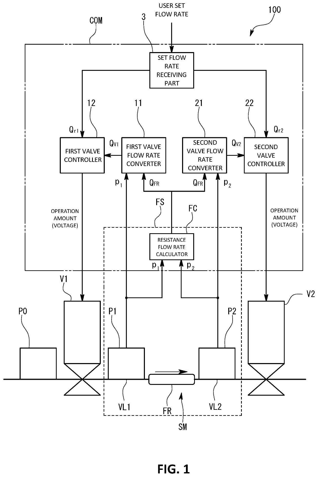
[0042]As shown in FIG. 1, the flow rate control apparatus 100 comprises fluid equipment composed of sensors and valves arranged in the flow channel, and a control operation mechanism (COM) that controls the fluid equipment.

[0043]The fluid equipment comprises a supply pressure sensor P0, a first valve V1, a first pressure sensor P1, a fluid resistor (FR), a second pressure sensor P2, and a second valve V2 arranged in the flow channel. Each component is arranged in this order from an upstream side in the flow channel.

[0044]In this embodiment, t...

second embodiment

[0069]Next, the flow rate control apparatus 100 according to the present claimed invention will be described with reference to FIG. 5.

[0070]The flow rate control apparatus 100 of the second embodiment further comprises a diagnizer (D) that self-diagnoses and calibrates the volumes of the first volume VL1 and the second volume VL2 in addition to the configuration for flow rate control explained in the first embodiment. More concretely, the diagnizer (D) performs a predetermined valve operation during a process stop period when no gas is supplied to the chamber and identifies a size of the first volume VL1 and the second volume VL2 based on the pressure change in the first volume VL1 or the second volume VL2 caused by the valve operation. In addition, the diagnizer (D) also identifies the first volume VL1 or the second volume VL2 based on the change in the first pressure p1 or the second pressure p2 that occurs when the first valve V1 and the second valve V2 are fully closed to tempor...

third embodiment

[0077]Next, the flow rate control apparatus 100 in a third embodiment will be described with reference to FIG. 6 and FIGS. 7(a) and 7(b).

[0078]The flow rate control apparatus 100 in the third embodiment differs from the first embodiment in the configuration of the first valve controller 12 and the second valve controller 22. More concretely, the first valve controller 12 changes a control coefficient based on the set flow rate and a differential pressure between the supply pressure and the first pressure. The second valve controller 22 changes the control coefficient based on the set flow rate and the differential pressure between the second pressure and a downstream side pressure. For this purpose, the first valve controller 12 is configured to obtain the supply pressure p0 from the supply pressure sensor PO and to obtain the first pressure p1 from the first pressure sensor P1. Similarly, the second valve controller 22 is configured to obtain the second pressure p2 from the second ...


PUM


Abstract

A flow rate control apparatus calculates a resistance flow rate, which is a flow rate of a fluid flowing through the fluid resistor, based on a first pressure measured by a first pressure sensor and a second pressure measured by a second pressure sensor, converts the resistance flow rate to a first valve flow rate, which is the flow rate of the fluid passing through a first valve, based on the first pressure, converts the resistance flow rate to a second valve flow rate, which is the flow rate of the fluid passing through a second valve, based on the second pressure, controls the first valve so that the deviation between a first set flow rate and the first valve flow rate becomes small, and controls the second valve so that the deviation between a second set flow rate and the second valve flow rate becomes small.

Description

FIELD OF THE ART[0001]The present claimed invention relates to a flow rate control apparatus for controlling, for example, a flow rate of a fluid.BACKGROUND ART[0002]In a semiconductor manufacturing process, various gases are supplied to a chamber in a controlled state with a desired flow rate. In recent years, high-speed control of the flow rate and further improvement of a flow rate accuracy have been required in this field (refer to the patent document 1), and a flow rate control apparatus using two control valves has been proposed to satisfy such requirements.[0003]Concretely, this flow rate control apparatus has an arrangement wherein a first valve, a pressure type flow rate sensor, and a second valve are arranged in this order from an upstream side in a flow channel. For example, the first valve is controlled by feeding back a first pressure of the first pressure sensor arranged in an upstream side of a laminar flow element that constitutes the flow rate sensor so that the fir...

Claims


Application Information

Patent Timeline
Patent Type & Authority Patents(United States)
IPC IPC(8): G05D7/06G01F1/36
CPCG05D7/0623G05D7/0647G01F1/363G05D7/0635Y10T137/7761F16K37/005F16K17/04
Inventor TOKUNAGA, KAZUYA
Owner HORIBA STEC CO LTD
Why Eureka
Try Eureka