Hydrothermal vent energy harvesting, storage, and power distribution system

a technology of hydrothermal vents and energy harvesting, applied in the direction of mechanical equipment, machines/engines, transportation and packaging, etc., can solve the problems of affecting the practical application of current methods of harvesting, storing and distributing such energy, corrosion of systems implemented, and serious problems, so as to minimize the potential problems arising from corrosion and fouling, and the effect of being easy to deploy

Active Publication Date: 2022-10-04
UNITED STATES OF AMERICA
View PDF6 Cites 0 Cited by
  • Summary
  • Abstract
  • Description
  • Claims
  • Application Information

AI Technical Summary

Benefits of technology

[0008]Another object is to provide a device that can be repositioned relative to the hydrothermal vent.
[0009]Yet another object is to provide a device that does not require blocking the entire thermal vent.
[0010]Accordingly, one embodiment provides a hydrothermal vent energy harvesting, storage, and distribution system. This includes a flotation device coupled to an energy storage device. The floatation device and energy storage device is located at or near an ocean surface. The system further comprises an energy harvesting unit coupled to the flotation device via a cable. The energy harvesting unit is positioned near a hydrothermal vent during energy harvesting. The embodiment can further include a positioning system (e.g., via the flotation device and coupled thrusters) so that hydrothermal energy from a vent may be converted to electrical energy us

Problems solved by technology

However, the location, depth range, and other physical characteristics of the vents pose challenges to accessibility and practical application of current methods for harvesting, storing, and distributing such energy.
For example, the pH of the hydrothermal fluid released from the vents and water in the surrounding area may be as low as 2.8 which can lead to significant corrosion of systems implemented in the harvesting, conversion, and transport of energy that may be used to power UUVs or other suitable devices.
Further,

Method used


Image

  • Hydrothermal vent energy harvesting, storage, and power distribution system
  • Hydrothermal vent energy harvesting, storage, and power distribution system
  • Hydrothermal vent energy harvesting, storage, and power distribution system

Examples


Embodiment Construction

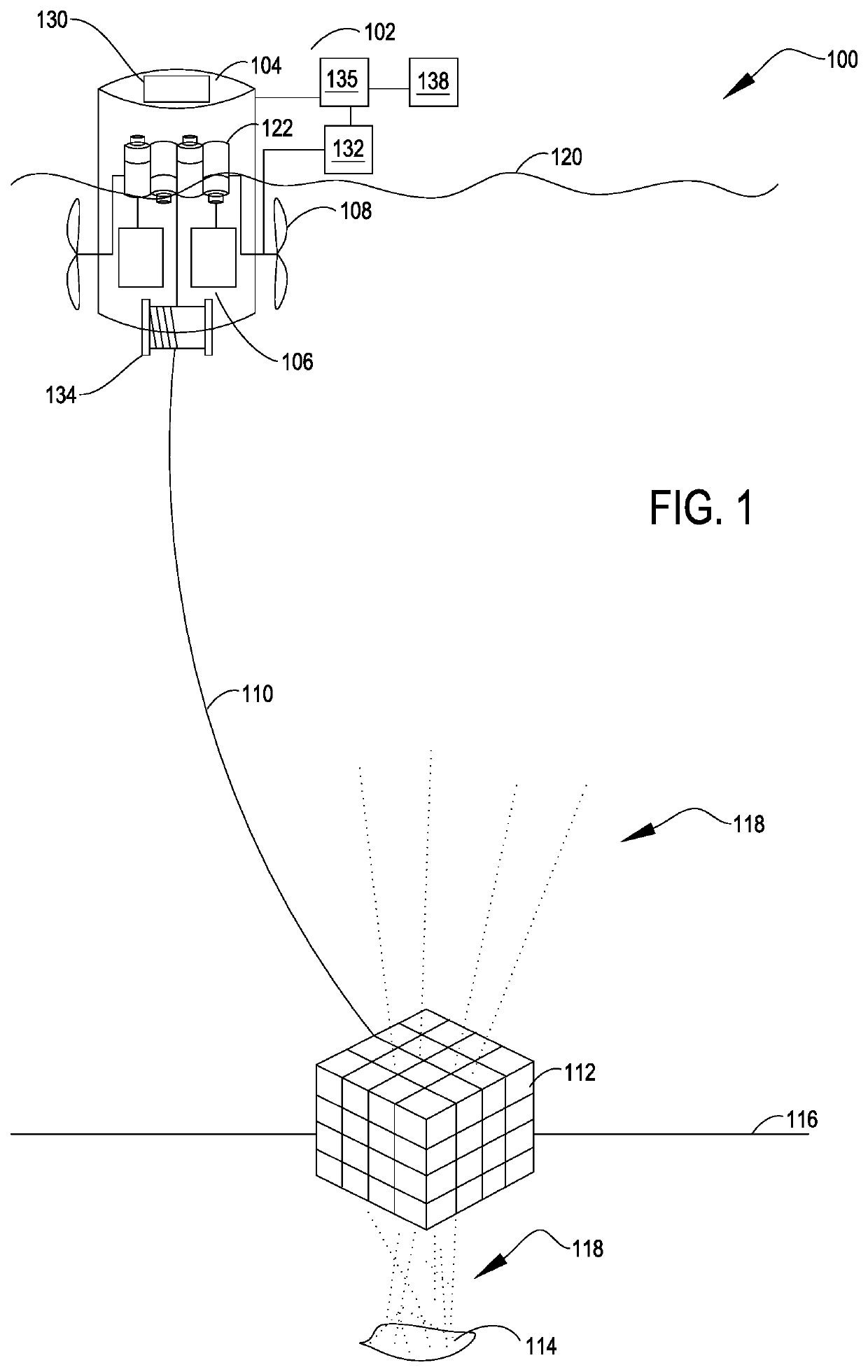
[0018]The following description relates to systems and methods for hydrothermal vent energy harvesting, storage, and power distribution systems that can be used to charge unmanned underwater vehicles (UUVs) and, more specifically, to charge the UUVs in an environmentally responsible manner. Generally, the system may be mobile, comprised of a simple energy harvesting unit (e.g., having few if any moving parts) positioned at or near a vent. The energy harvesting unit is physically and operatively coupled to flotation and energy storage or distribution devices located at or near an ocean surface via a cable. The energy harvesting unit may be strategically positioned (e.g., via a buoy and a coupled positioning system) to convert heat energy from the vent into commanded and / or demanded electrical energy, with the electrical energy transferred to the energy storage / distribution devices at the surface via the cable. The energy storage / distribution devices may be communicatively coupled to ...


PUM


Abstract

An energy harvesting system is positionable at an ocean surface to harvest energy from a hydrothermal vent surrounded by cooler ocean water. The system includes an energy storage device positionable proximate to the ocean surface. A cable capable of conducting electrical energy is joined to the energy storage device. An energy harvesting structure is joined to provide electrical energy to the cable. The energy harvesting structure can be positioned proximate to the hydrothermal vent to harvest energy therefrom.

Description

STATEMENT OF GOVERNMENT INTEREST[0001]The invention described herein may be manufactured and used by or for the Government of the United States of America for governmental purposes without the payment of any royalties thereon or therefor.CROSS REFERENCE TO OTHER PATENT APPLICATIONS[0002]None.BACKGROUND OF THE INVENTION(1) Field of the Invention[0003]The present invention is directed to a thermal energy harvesting and distribution system and more particularly to a system utilizing energy from an ocean thermal vent.(2) Description of the Prior Art[0004]Interest in energy harvesting from ocean thermal vents is ongoing. The high temperatures (e.g., typically around 350° Celsius) of sea-floor hydrothermal vents make them attractive targets for the exploitation of thermal energy that may be used to generate electric power for unmanned underwater vehicles (UUVs). However, the location, depth range, and other physical characteristics of the vents pose challenges to accessibility and practic...

Claims


Application Information

Patent Timeline
IPC IPC(8): F03B13/26H02J50/00H02J7/00F03G7/05B63B35/44H01L35/28
CPCH02J50/001B63B35/44F03G7/05H02J7/0013B63B2035/4466H01L35/28H02J7/0045H02J7/0048H10N10/10
Inventor KUKLINSKI, ROBERTRUFFA, ANTHONY A
Owner UNITED STATES OF AMERICA
Why Eureka
Try Eureka