Control method for an impact wrench

a control method and wrench technology, applied in the direction of wrenches, power driven tools, screwdrivers, etc., can solve the problems that the combined control methods are each in and of themselves not suitable for securely fastening steel components, and achieve the effect of reliable tightening of screw elements

Active Publication Date: 2022-10-11
HILTI AG
View PDF8 Cites 0 Cited by
  • Summary
  • Abstract
  • Description
  • Claims
  • Application Information

AI Technical Summary

Benefits of technology

[0005]The combined control methods are each in and of themselves not suitable for securely fastening steel components with the aid of an electromechanical impact wrench, using screwing elements, e.g. screws, bolts, nuts. However, the combination of the two methods makes it possible to reliably tighten the screw elements using the limited sensory means of an impact wrench.

Problems solved by technology

The combined control methods are each in and of themselves not suitable for securely fastening steel components with the aid of an electromechanical impact wrench, using screwing elements, e.g. screws, bolts, nuts.

Method used


Image

  • Control method for an impact wrench
  • Control method for an impact wrench
  • Control method for an impact wrench

Examples


Embodiment Construction

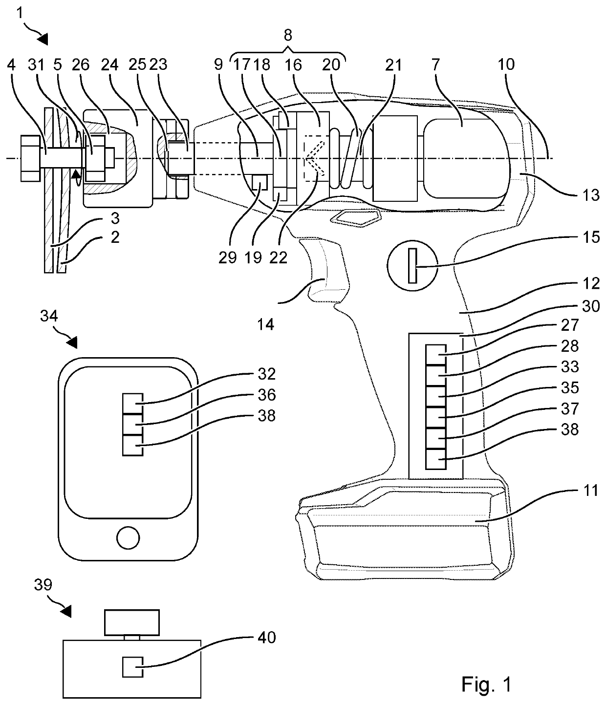
[0015]FIG. 1 schematically shows the configuration of an impact wrench 1. One application of impact wrench 1 is to screw a steel plate 2 to a steel beam 3. Steel plate 2 and steel beam 3 are connected to each other by a screw 4 and a nut 5. Typical steel plates and steel beams have undefinedly domed surfaces, which apply a counter-force similar to a steel spring when screwed together. Impact wrench 1 supports the user in a secure screwing action. The steel plate should planarly abut the steel beam, and screw 4 should not be overexpanded.

[0016]Screw 4 or nut 5 is tightened in two phases. The screw head of screw 4 is advantageously fixed and nut 5 is tightened.

[0017]In the first phase, nut 5 is tightened until screw 4 is expanded to approximately 40% to 60% of its yield strength. The expansion is not measured directly but estimated with the aid of an individual impact angle theta, around which nut 5 rotates due to a single impact. It is recognized that, for the targeted range of the y...


PUM


Abstract

A control method includes two operating modes carried out in response to a position of a selector switch. The first operating mode provides: carrying out first impacts of the hammer onto the anvil; detecting the event of an impact of the hammer onto the anvil with an impact sensor; detecting an angular position of the anvil with an angle sensor; estimating an individual impact angle of the anvil due to the last detected impact, based on the angular position of the anvil before the last detected impact and the angular position of the anvil after the last detected impact, and comparing the individual impact angle with an individual impact setpoint angle. The first operating mode is ended when the individual impact angle drops below an individual impact setpoint angle. The second operating mode provides: detecting the angular position of the anvil with the angle sensor as the initial position; carrying out second impacts of the hammer onto the anvil; and detecting a relative rotation angle of the anvil with respect to the initial position during the second impacts. The second operating mode is ended when the relative rotation angle exceeds a standard angle.

Description

[0001]The present invention relates to a control method for an impact wrench for fastening steel components with the aid of screw connections.SUMMARY OF THE INVENTION[0002]The present invention provides a control method that has two operating modes, which are carried out in response to a position of a selector switch. The first operating mode provides the following steps:[0003]Carrying out first impacts of the hammer onto the anvil; detecting the event of an impact of the hammer onto the anvil with the aid of an impact sensor; detecting an angular position of the anvil with the aid of an angle sensor; estimating an individual impact angle of the anvil due to the last detected impact, based on the angular position of the anvil before the last detected impact and the angular position of the anvil after the last detected impact, and comparing the individual impact angle to an individual impact setpoint angle. The first operating mode is ended when the individual impact angle drops belo...

Claims


Application Information

Patent Timeline
Patent Type & Authority Patents(United States)
IPC IPC(8): B25B21/02B25B23/147
CPCB25B21/026B25B21/02B25B23/1475
Inventor WOETZL, CHRISTIANBRALLA, DARIOALBERDING, MATTHAEUS
Owner HILTI AG
Why Eureka
Try Eureka