
Free orientation fourier camera

a fourier camera and free orientation technology, applied in the field of imaging techniques, can solve the problems of many melanomas, difficult to distinguish mole growth from image distortion, and local extensive or metastasiz

Active Publication Date: 2022-10-11
CALIFORNIA INST OF TECH
View PDF225 Cites 3 Cited by
  • Summary
  • Abstract
  • Description
  • Claims
  • Application Information

AI Technical Summary

Benefits of technology

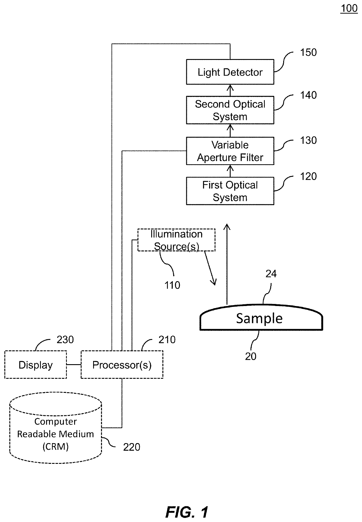
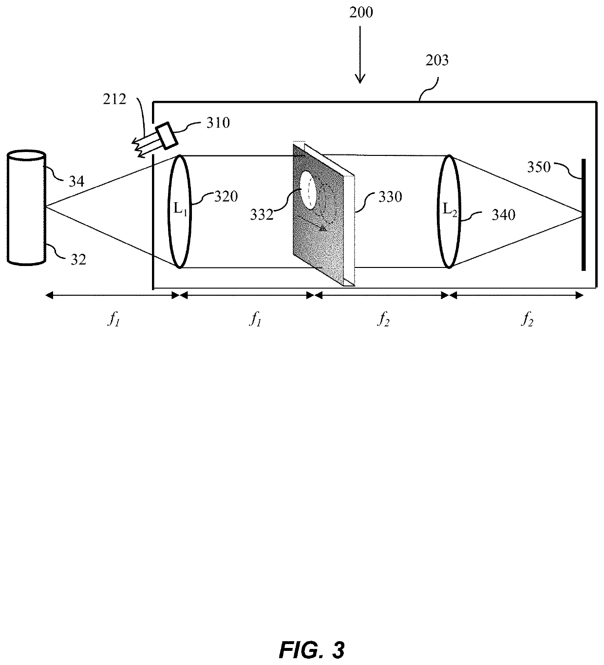
This patent is about a new type of camera called a Fourier camera that can capture very precise images of curved surfaces. The camera has two optical systems and a special filter that moves to different positions in the camera to filter the light from the first optical system. This results in a series of raw images that are then combined to create a high-quality image of the curved surface. The technical effect of this invention is that it allows for the capture of detailed and uniform images of curved surfaces, which was previously difficult to achieve with traditional cameras.

Problems solved by technology

Though excision can be curative at early stages, many melanomas are not detected in time and may become locally extensive or metastasize to other locations.
If distance and orientation are not maintained, magnification, focus, and orientation of the mole images may vary, making it difficult to distinguish mole growth from image distortion.
When imaging a mole on a curved skin surface (such as on the bridge of the nose), a single adjustable plane may provide poor image quality across the mole.
For these reasons, it can be difficult to use conventional cameras to detect subtle changes in moles.

Method used


Image

  • Free orientation fourier camera
  • Free orientation fourier camera
  • Free orientation fourier camera

Examples


Embodiment Construction

[0025]Embodiments of the present invention will be described below with reference to the accompanying drawings. The features illustrated in the drawings may not be to scale. Certain aspects described herein pertain to Fourier camera systems and Fourier camera methods.

[0026]I. Fourier Camera Systems

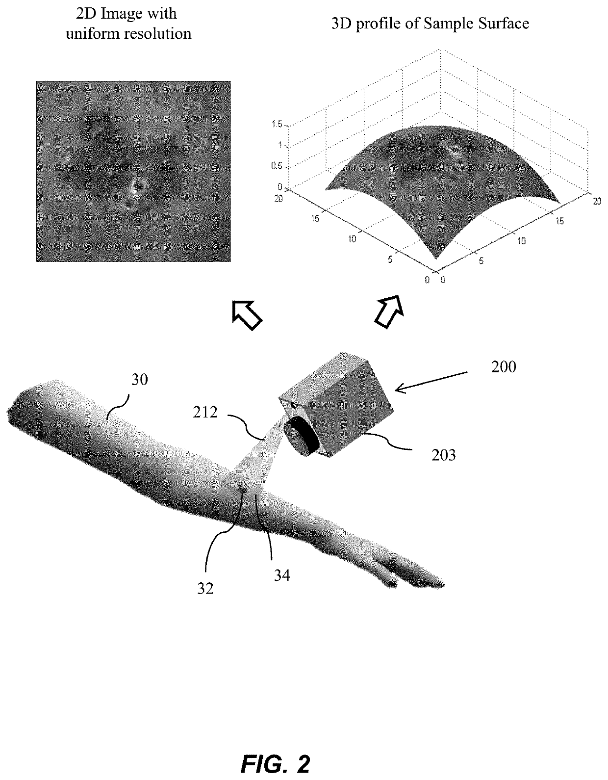
[0027]Certain embodiments pertain to Fourier camera systems / methods that can generate a topological 3-D and substantially uniformly high resolution image of a curved sample surface at each imaging cycle. These Fourier camera systems / methods can use these uniform resolution 3-D profile images to account for position, orientation, and magnification changes between imaging cycles as may occur, for example, in a handheld imaging device. Embodiments of Fourier camera systems and methods that can account for position and orientation changes between imaging cycles are described as “free orientation,” which may provide robust techniques for tracking mole growth or changes to another object of inte...


PUM


Abstract

Certain aspects pertain to Fourier camera systems and methods. In one aspect, a Fourier camera comprises a first optical system, a second optical system, a variable aperture filter, and a light detector. The first optical system configured to receive illumination reflected from a curved sample surface. The variable aperture filter configured to move an aperture to a plurality of aperture locations in a Fourier plane, wherein the aperture filters light from the first optical system to the second optical system. The light detector configured to receive light from the second optical system, and configured to acquire a plurality of raw intensity images of the curved sample surface corresponding to the plurality of aperture locations, wherein the raw images are iteratively updated in overlapping regions in Fourier space to generate a focused, substantially uniform resolution image of the curved sample surface, and wherein the overlapping regions correspond to the plurality of aperture locations.

Description

CROSS-REFERENCES TO RELATED APPLICATIONS[0001]This application claims benefit of and priority to U.S. Provisional Patent Application No. 61 / 952,318 titled “Free Orientation Fourier Camera,” filed on Mar. 13, 2014, which is hereby incorporated by reference in its entirety and for all purposes.BACKGROUND[0002]Certain embodiments described herein are generally related to imaging techniques, and more specifically, to methods, devices, and systems for Fourier camera imaging in applications such as, for example, photography for mole tracking.[0003]Melanoma is currently the leading cause of cancer-related deaths among Americans (almost 10,000 deaths annually) with over 75,000 new cases annually. The incidence of melanoma has been rising steadily. Though excision can be curative at early stages, many melanomas are not detected in time and may become locally extensive or metastasize to other locations. Early detection of melanoma is critical to reduce its morbidity and mortality. In approxim...

Claims


Application Information

Patent Timeline
Patent Type & Authority Patents(United States)
IPC IPC(8): G06T7/00G02B27/46A61B5/00
CPCG06T7/0012G02B27/46A61B5/0059A61B5/444
Inventor OU, XIAOZEYANG, CHANGHUEI
Owner CALIFORNIA INST OF TECH
Learn More