Track maintenance machine for compaction of ballast

a technology of ballast and maintenance machine, which is applied in the direction of locomotives, vehicles, ways, etc., can solve the problem that a part of electric energy must be intermediately stored

Active Publication Date: 2022-10-25
PLASSER & THEURER EXPORT VON BAHNBAUMASCHINEN GESELLSCHAFT MBH
View PDF7 Cites 0 Cited by
  • Summary
  • Abstract
  • Description
  • Claims
  • Application Information

AI Technical Summary

Benefits of technology

[0007]In an advantageous embodiment of the invention, the electric energy store comprises a super capacitor. With this, a high power density can be achieved in a small space and with little weight. In addition, a super capacitor allows a quick discharge and a sufficient number of charging- and discharging cycles, thus optimally supporting the vibration drive having recurring and suddenly increasing performance peaks.
[0017]In an improved method, the tamping tools are actuated with a higher vibration frequency during penetration into the ballast than during a squeezing operation. This makes possible an easier penetration into the ballast bed and thus shorter tamping cycles. Additionally, the increased vibration frequency and the reduced ballast resistance thus achieved have a favourable effect on the wear and tear of the tamping tools.

Problems solved by technology

During this, only a part of the electric energy has to be intermediately stored because the energy consumption by the vibration drive starts already during a braking procedure of the track maintenance machine.

Method used


Image

  • Track maintenance machine for compaction of ballast
  • Track maintenance machine for compaction of ballast

Examples


Embodiment Construction

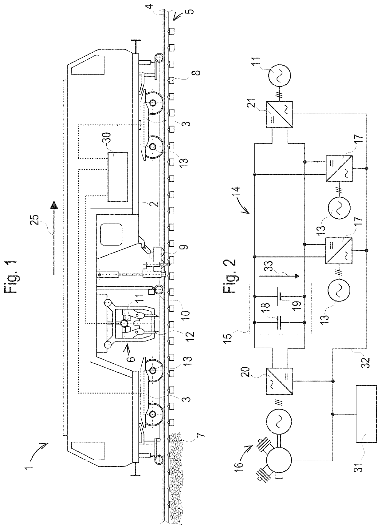
[0022]The track maintenance machine 1 shown in FIG. 1 comprises a machine frame 2 which is mobile by means of undercarriages 3 on rails 4 of a track 5. A tamping unit 6 for compaction of ballast 7 under sleepers 8 of the track 5 is arranged on the machine frame 2. Prior to a compaction operation, the track 5 is brought into a target position, specified by a measuring system 10, by means of a lifting-lining unit 9.

[0023]The tamping unit 6 comprises an electric vibration drive 11 for vibratory actuation of tamping tools 12. In addition, hydraulic drives are provided for lowering or lifting as well as for squeezing the tamping tools 12 together. Advantageously, the vibration drive 11 is built as a brushless electric motor.

[0024]The present example shows a track maintenance machine 1 with cyclic working mode, since during a working run the entire track maintenance machine 1 is moved from sleeper 8 to sleeper 8. In this, the tamping tools 12 plunge into sleeper cribs located between the ...


PUM


Abstract

A track maintenance machine for compaction of ballast under sleepers of a track includes a machine frame movable by undercarriages on the track and a tamping unit which includes an electric vibration drive for vibratory actuation of tamping tools. An electric intermediate circuit has an electric energy store or storage device. An electric machine is associated with at least one undercarriage and coupled for generator operation to the intermediate circuit. The electric vibration drive is coupled to the intermediate circuit for supply. In this way, braking energy is used in an optimal manner for supplying the vibration drive. A method for operation of a track maintenance machine is also provided.

Description

BACKGROUND OF THE INVENTIONField of the Invention[0001]The invention relates to a track maintenance machine for compaction of ballast under sleepers of a track, having a machine frame mobile by means of undercarriages on the track and a tamping unit which comprises an electric vibration drive for vibratory actuation of tamping tools. In addition, the invention relates to a method for operating the track maintenance machine.Description of the Related Art[0002]A track maintenance machine having a tamping unit comprising an electric vibration drive for vibratory actuation of tamping tools is known, for example, from DE 24 17 062 A1. In this, eccentric bearing bushings are arranged in pivot arms to generate vibrations. Via a chain drive, a rotary motion is transmitted to the eccentric bearing bushings by a drive shaft powered by an electric motor.[0003]According to Austrian Patent Application A 179 / 2017, a tamping unit with a central vibration drive is known, wherein the vibration is tr...

Claims


Application Information

Patent Timeline
Patent Type & Authority Patents(United States)
IPC IPC(8): E01B27/17E01B27/02
CPCE01B27/17E01B27/028E01B27/12E01B27/16B61C3/02B61D43/00Y02T30/00
Inventor STADLER, LOTHAR
Owner PLASSER & THEURER EXPORT VON BAHNBAUMASCHINEN GESELLSCHAFT MBH
Why Eureka
Try Eureka