Supercharge Your Innovation With Domain-Expert AI Agents!

Ground wing portion for electronic package device

a technology of electronic package device and ground wing portion, which is applied in the direction of solid-state device, magnetic/electric field screening, basic electric elements, etc., can solve the problems of power noise and power integrity decline, and achieve the effect of improving power integrity and power integrity

Active Publication Date: 2022-10-25
ALICORP
View PDF9 Cites 0 Cited by
  • Summary
  • Abstract
  • Description
  • Claims
  • Application Information

AI Technical Summary

Benefits of technology

The patent describes an electronic package device and a carrier structure that improve power integrity. This is achieved by a ground wing portion that is connected to a ground frame and located under the pin assembly. The ground wing portion has an extending part and a joint part, with the top end of the extending part positioned above the bottom surface of a die attach paddle. This reduces a loop area defined by a current path, resulting in better power performance.

Problems solved by technology

However, when the parasitic inductance becomes too large, signal impedance mismatch, power noise, and a decrease of power integrity may occur.

Method used


Image

  • Ground wing portion for electronic package device
  • Ground wing portion for electronic package device
  • Ground wing portion for electronic package device

Examples


first embodiment

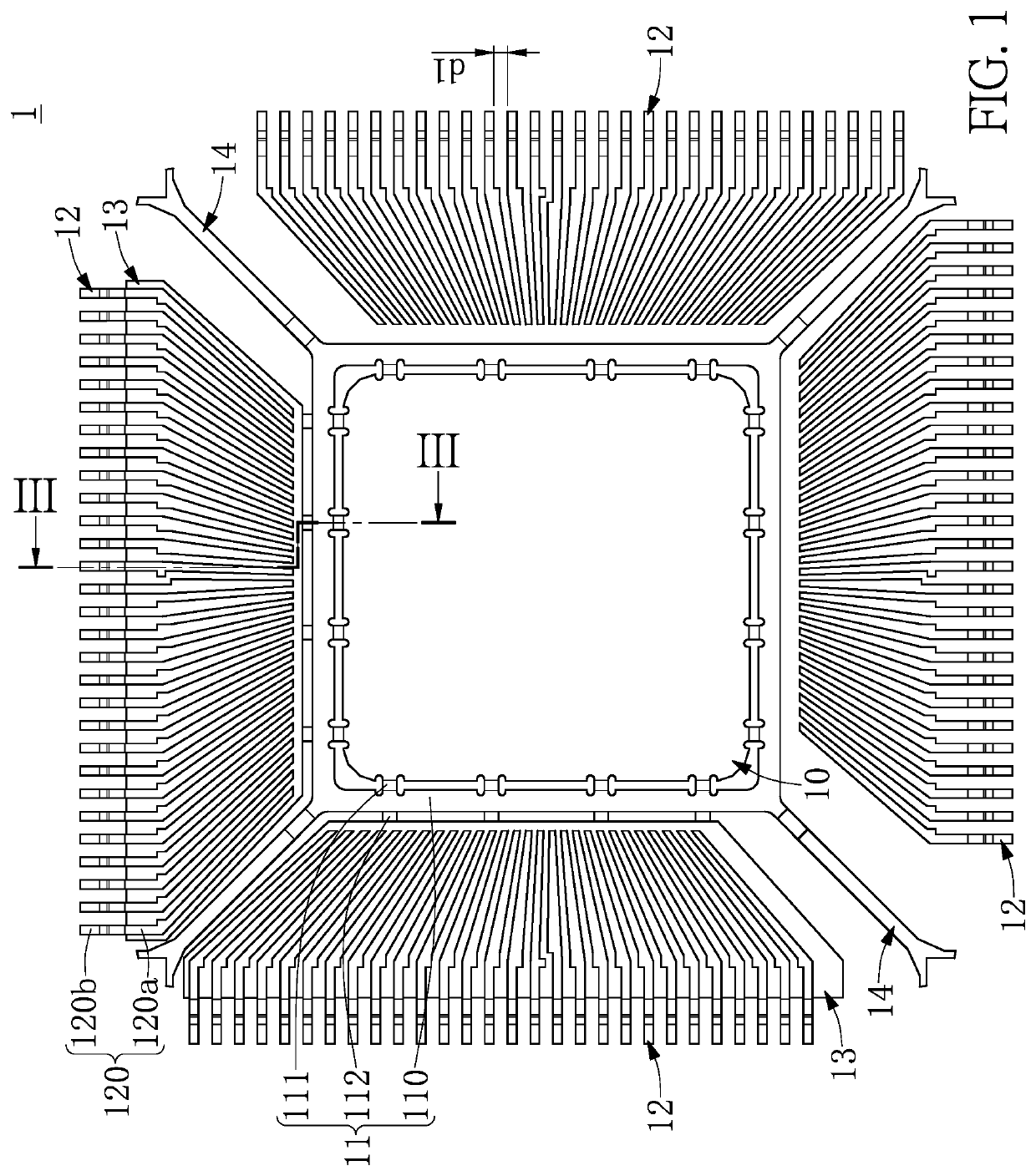
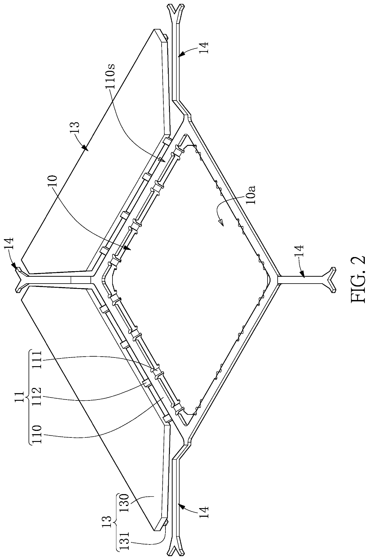
[0034]Reference is made to FIG. 1 and FIG. 2. FIG. 1 is a schematic top view of a carrier structure according to a first embodiment of the present disclosure, and FIG. 2 shows a perspective schematic view of the carrier structure shown in FIG. 1, in which the pin assembly is omitted. The carrier structure 1 can be used to support a chip, so that the chip can be electrically connected to an external circuit. Accordingly, during operation of the chip, the carrier structure 1 is also used to transmit high-frequency signals.

[0035]As shown in FIG. 1, the carrier structure 1 of the embodiment provided in the present disclosure includes a die attach paddle 10, a ground frame 11, a pin assembly 12, and at least one ground wing portion 13.

[0036]In the instant embodiment, the die attach paddle 10 is used to support the chip and has a supporting surface 10a and a bottom surface 10b opposite to the supporting surface 10a. The ground frame 11 surrounds and is connected to the die attach paddle 1...


PUM


Abstract

An electronic package device and a carrier structure thereof are provided. The carrier structure includes a die attach paddle, a ground frame, a pin assembly, and a ground wing portion. The ground frame surrounds the die attach paddle. The pin assembly includes a plurality of pins that are spaced apart from one another. The pins extend radially outward and are arranged to surround the ground frame. The ground wing portion is connected to the ground frame and located in a space under the pin assembly. The ground wing portion includes an extending part and a joint part, the extending part extends away from the die attach paddle, and a top end of the extending part is located at a position above where a bottom surface of the die attach paddle is located.

Description

CROSS-REFERENCE TO RELATED PATENT APPLICATION[0001]This application claims the benefit of priority to China Patent Application No. 202010764568.6, filed on Jul. 31, 2020 in People's Republic of China. The entire content of the above identified application is incorporated herein by reference.[0002]Some references, which may include patents, patent applications and various publications, may be cited and discussed in the description of this disclosure. The citation and / or discussion of such references is provided merely to clarify the description of the present disclosure and is not an admission that any such reference is “prior art” to the disclosure described herein. All references cited and discussed in this specification are incorporated herein by reference in their entireties and to the same extent as if each reference was individually incorporated by reference.FIELD OF THE DISCLOSURE[0003]The present disclosure relates to an electronic package device and a carrier structure there...

Claims


Application Information

Patent Timeline
Patent Type & Authority Patents(United States)
IPC IPC(8): H01L23/495H01L23/48H01L21/00H05K7/10H05K9/00H05K7/18H01L23/498H01L21/56H01L23/31H01L23/00
CPCH01L23/49551H01L21/56H01L23/3107H01L23/4952H01L23/49503H01L23/49555H01L23/49838H01L24/48H01L2224/48245H01L2224/48257H01L2924/182H01L23/49541H01L23/49537H01L23/49548H01L2224/04042H01L2224/48247H01L2224/49109H01L2924/15156H01L24/49H01L2924/3025H01L2224/32245H01L2924/30107
Inventor LIN, CHIN-SUNG
Owner ALICORP
Features
  • R&D
  • Intellectual Property
  • Life Sciences
  • Materials
  • Tech Scout
  • Unparalleled Data Quality
  • Higher Quality Content
  • 60% Fewer Hallucinations
Learn More