High-torque ratchet wrench
- Summary
- Abstract
- Description
- Claims
- Application Information
AI Technical Summary
Benefits of technology
Problems solved by technology
Method used
Image
Examples
embodiment 1
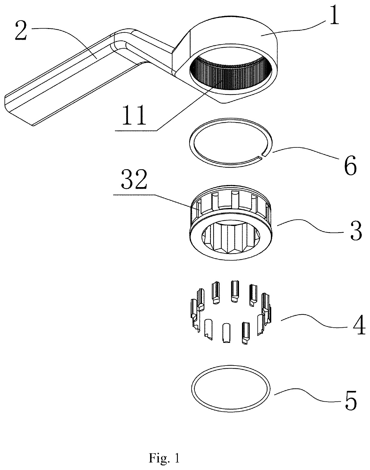
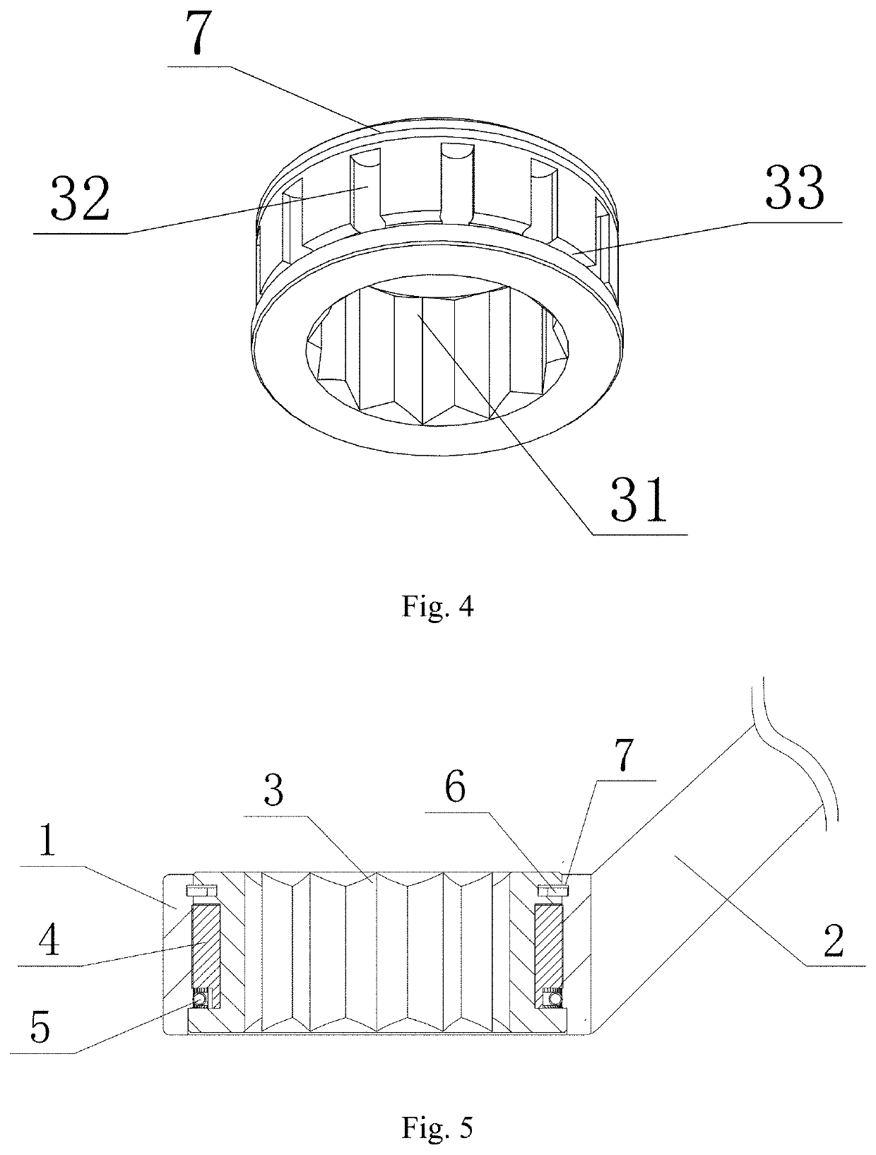
[0040]As illustrated in FIG. 1, the wrench in this embodiment comprises a wrench body having a driving aperture 1 and a handle 2, wherein the driving aperture 1 has the structure of a rounded through hole and has only one end disposed on the handle 2, a drive member 3 is arranged in the driving aperture 1 and an axial position-limiting mechanism is used to prevent the drive member 3 from axially moving from the driving aperture 1 and further being released from the driving aperture 1, and the axial position-limiting mechanism in this embodiment is realized by adopting the structure of a snap spring 6 mounted in a snap spring recess 7 as shown in FIGS. 4-5; As illustrated in FIG. 4, a through hole 31 having a quincuncial section is arranged in the center of a drive member 3 to fit a fastener, such as bolts, so as to transfer the rotational torque from the handle 2 to the fastener.
[0041]As illustrated in FIGS. 1, 4, 5 and 6, the external side wall of the drive member 3 and the inner h...
embodiment 2
[0056]As illustrated in FIGS. 9, 10, 11, 12 and 13, the difference from Embodiment 1 is that the ratchet teeth 12 are evenly arranged on the inner hole wall 11 of the driving aperture 1 in this embodiment, the extension direction of the ratchet teeth 12 is parallel to the central axis of the driving aperture 1 and both sides of the convex part are in the shape of tool edge so that convex part 41 can form a ratchet structure matching the ratchet teeth 12.
[0057]The principle of engagement of the ratchet teeth 12 with the relief 41 (i.e. snap teeth, the same below) is similar to that in Embodiment 1, as shown below:
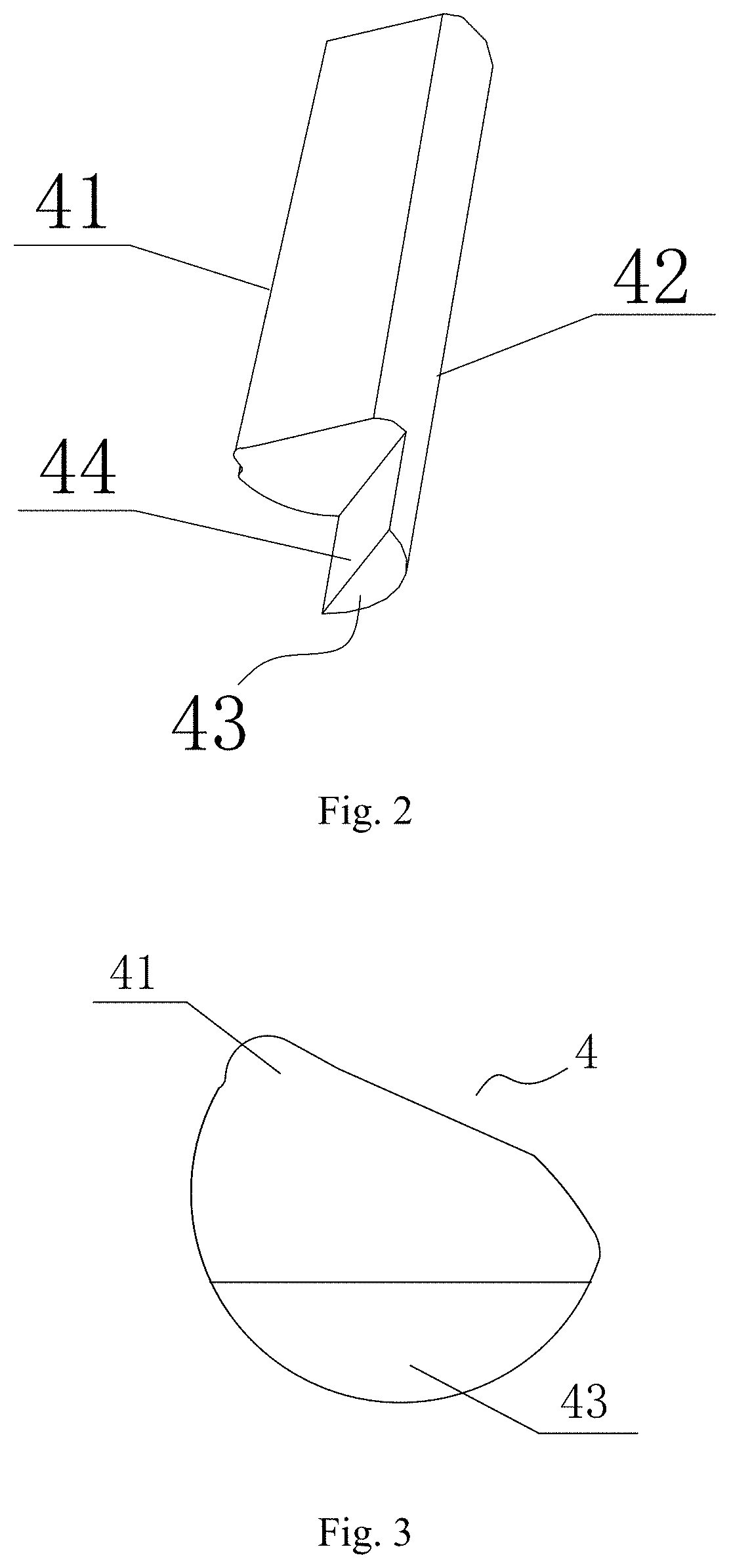
[0058]As illustrated in FIG. 12, the spring ring 5 contracts under the spring force, the spring ring 5 applies to the bearing face 44 of the pin 4 the elastic force which tends towards the center of the spring ring 5 (i.e. the central axis of the driving aperture 1) pushes the pin 4 to rotate clockwise (as shown in the dotted arrow in FIG. 7) so as to make the relief 41 of t...
embodiment 3
[0063]As illustrated in FIGS. 14, 15 and 16, the difference from Embodiment 2 is that the inner hole wall 11 of the driving aperture 1 is used as the first drive face having the pin recess 32 and the external side face of the drive member 3 is used as the second drive face having the ratchet teeth 12 in this embodiment, and for other structures and operating principles of this embodiment, refer to Embodiment 2, so they will not be repeated herein.
[0064]It is understood that the spring ring 5 in Embodiments 1, 2 and 3 described above can also be arranged in a circle surrounded by all pins 4, and the spring ring 5 is pressed against the bearing face 44 of the spring pressing portion 43 of all pins 4 at the same time, and the elastic force that is produced by outward expansion of the spring ring 5 is employed to reset the pins 4.
[0065]In addition, FIGS. 17 and 18 illustrate the wrenches having two different structures, wherein:
[0066]in the wrench as shown in FIG. 17, both ends of the h...
PUM
 Abstract
Description
Claims
Application Information
 - R&D
- Intellectual Property
- Life Sciences
- Materials
- Tech Scout
- Unparalleled Data Quality
- Higher Quality Content
- 60% Fewer Hallucinations
Browse by: Latest US Patents, China's latest patents, Technical Efficacy Thesaurus, Application Domain, Technology Topic, Popular Technical Reports.
© 2025 PatSnap. All rights reserved.Legal|Privacy policy|Modern Slavery Act Transparency Statement|Sitemap|About US| Contact US: help@patsnap.com


