Heat sink and method for making the same

a heat sink and heat sink technology, applied in the direction of lighting and heating apparatus, metal-working apparatus, semiconductor devices, etc., can solve the problems of degrading the heat dissipation capability affecting the heat dissipation efficiency of the heat sink, and unable to effectively transmit heat generated by the chip

Inactive Publication Date: 2001-05-31
LEE SHUN JUNG +1
View PDF0 Cites 5 Cited by
  • Summary
  • Abstract
  • Description
  • Claims
  • Application Information

AI Technical Summary

Benefits of technology

[0010] Another object of the present invention is to provide a heat sink having its fins and its base plate securely integrated with each other to enhance the heat dissipating efficiency of the heat sink.
[0012] A method for making a reliable heat sink of the present invention is also provided. The method includes a preparing step, a punching step and a flattening step. The preparing step comprises manufacturing a base plate and a plurality of fins each including a connecting portion and a heat dissipating portion. The punching step comprises punching the connecting portions of the fins against the base plate so that they integrate with the base plate in such manner that concave sections are left in the connecting portions and convex sections are left on a lower surface of the base plate. The flattening step comprises flattening the convex sections of the base plate to maintain planarity of the base plate. Using this method, the fins are securely integrated with the base plate thereby enhancing the heat dissipating efficiency of the heat sink.

Problems solved by technology

As chips such as microprocessors contain more circuitry and operate at faster speeds, greater amounts of heat are generated, which must be effectively and timely dissipated, otherwise a malfunction or operational instability of the computer will result.
However, due to clearances inevitably defined between the fins and the base plate, the heat generated by the chip can not be effectively transmitted from the base plate to the fins, thereby significantly degrading the heat dissipating capability of the heat sink.
Although no clearance exists between the heat dissipating member and the base plate, the heat dissipating member and the base plate may separate from each other if the bond fails.
In addition, since the adhesive is a material having poor heat conducting capability, the heat dissipating efficiency of the heat sink is also degraded.

Method used


Image

  • Heat sink and method for making the same
  • Heat sink and method for making the same
  • Heat sink and method for making the same

Examples


first embodiment

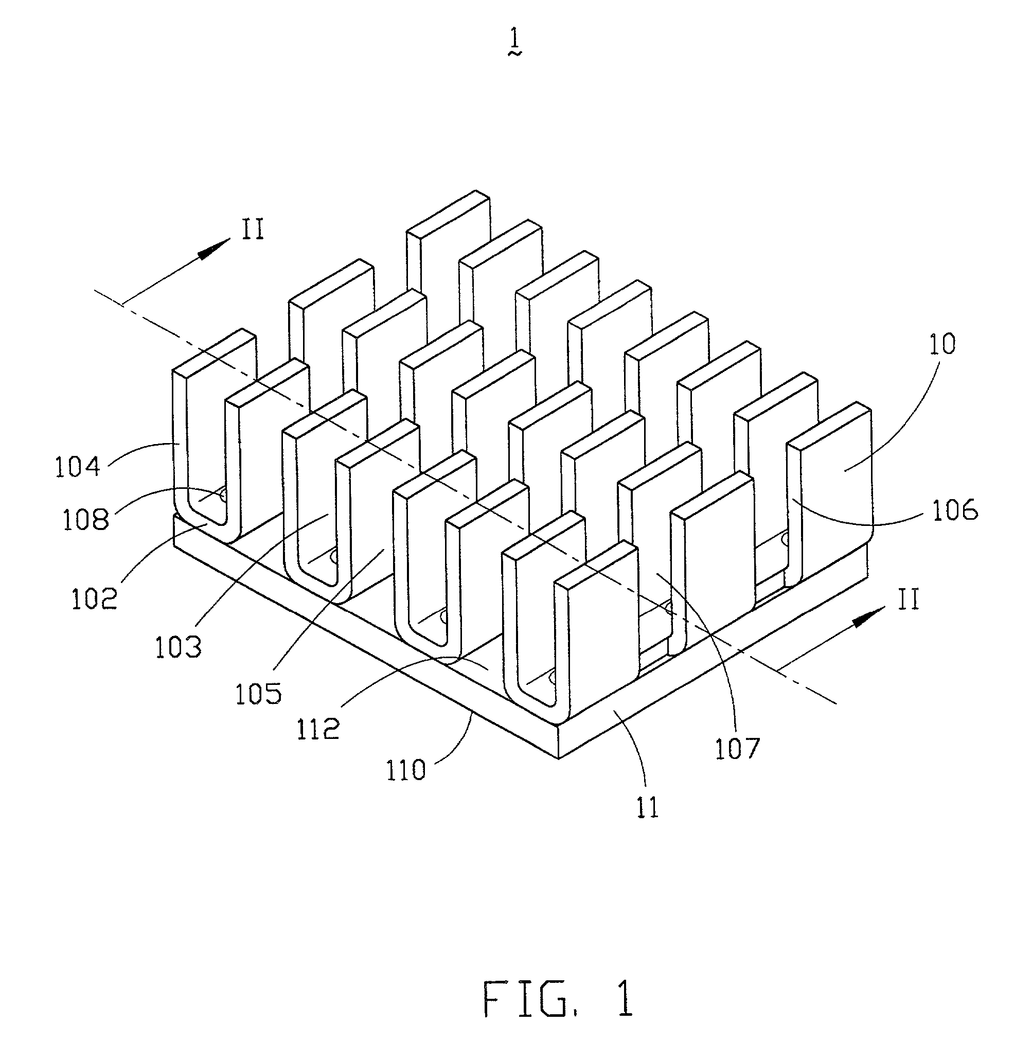
[0025] Referring to FIG. 1, a heat sink 1 in accordance with the present invention comprises a flat base plate 11 and a plurality of heat dissipating fins 10 upwardly extending from the base plate 11. The base plate 11 and the fins 10 are made from a heat conductive material such as aluminum and are integrated with each other by punching.

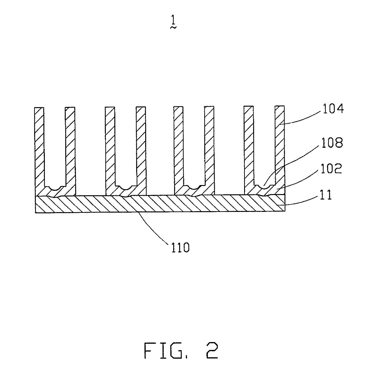
[0026] The base plate 11 has a lower surface 110 for contacting a heat generating component in a computer and an upper surface 112 for disposing the fins 10. The fins 10 are formed by shearing and bending and are arranged in rows. Each fin 10 has a U-shaped cross section forming a connecting portion in the form of a strip 102 and a heat dissipating portion in the form of a pair of opposite side walls 104.

[0027] The opposite side walls 104 of each fin 10 define a first channel 103 in a transverse direction of the heat sink 1. A second channel 105 is defined between adjacent rows of fins 10 in a direction parallel with the first channel 103. The fins ...

second embodiment

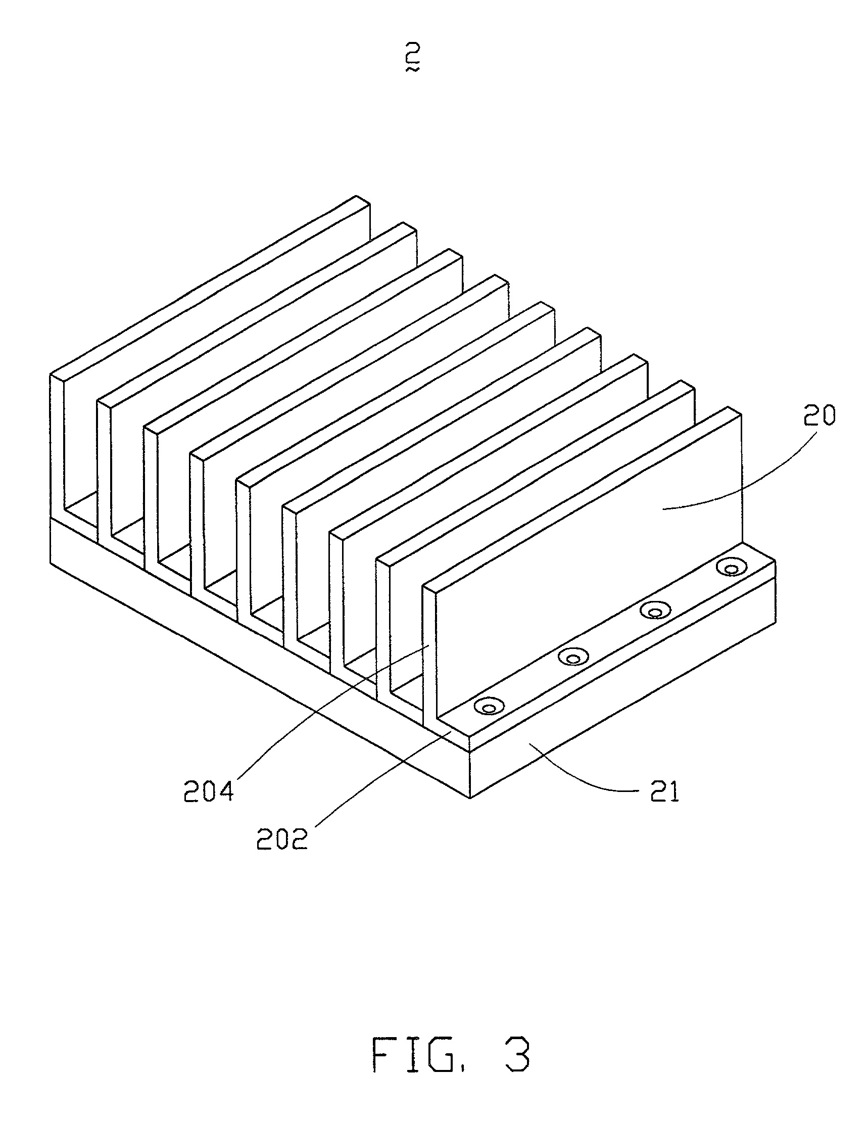
[0029] FIG. 3 shows a heat sink 2 in accordance with the present invention. The heat sink 2 comprises a base plate 21 and a plurality of parallel fins 20. Each fin 20 has an L-shaped cross section and is formed by bending. Each fin 20 includes a connecting portion in the form of a strip 202 and a heat dissipating portion in the form of a vertical wall 204. The strips 202 of the fins 20 are securely integrated with the base plate 21 by punching.

third embodiment

[0030] A heat sink 3 in accordance with the present invention is shown in FIGS. 4 and 5. The heat sink 3 includes a base plate 31 and a plurality of fins 30 formed by shearing and bending. Each fin 30 includes a heat dissipating portion in the form of a central vertical wall 304 and a connecting portion in the form of a plurality of tabs 302 extending from opposite sides of the vertical wall 304 in a staggered manner. The tabs 302 of the fins 30 are securely integrated with the base plate 31 by punching whereby the staggered tabs 302 of adjacent fins 30 are engaged with each other, as best shown in FIG. 5.


PUM

PropertyMeasurementUnit
heat dissipating efficiencyaaaaaaaaaa
speedsaaaaaaaaaa
heat conductiveaaaaaaaaaa

Abstract

A heat sink includes a base plate and a plurality of heat dissipating fins upwardly extending from the base plate. Each fin includes a heat dissipating portion and a connecting portion integrated with the base plate by punching whereby concave sections are left in the connecting portion. The fins can be formed in various shapes by shearing and bending or by bending a metal sheet. A method for making a reliable heat sink includes a preparing step, a punching step and a flattening step. The preparing step comprises manufacturing a base plate and a plurality of fins each including a connecting portion and a heat dissipating portion. The punching step comprises punching the connecting portions of the fins against the base plate thereby integrating the connecting portions with the base plate, forming concave sections in the connecting portions and convex sections on an opposite lower surface of the base plate. The flattening step comprises flattening the convex sections of the base plate to maintain the planarity of the base plate.

Description

[0001] This is a Division of U.S. patent application Ser. No. 09 / 414,220, filed on Oct. 6, 1999, which is now pending.[0002] 1. Field of the Invention[0003] The present invention relates to a heat sink and a method for making the same, and particularly to a reliable heat sink with enhanced heat dissipating efficiency and a method for making the same.[0004] 2. Description of Prior Art[0005] As chips such as microprocessors contain more circuitry and operate at faster speeds, greater amounts of heat are generated, which must be effectively and timely dissipated, otherwise a malfunction or operational instability of the computer will result. Conventionally, a heat sink made from a heat conductive material, such as aluminum, is commonly used to remove the heat generated by a heat generating component, such as a CPU (central processing unit) or a chip in a computer. The heat sink is retained in direct contact with the heat generating component to dissipate the heat into the surrounding e...

Claims


Application Information

Patent Timeline
Patent Type & Authority Applications(United States)
IPC IPC(8): F28F3/02H01L23/367
CPCF28F3/02H01L23/3672H01L2924/0002H01L2924/00Y10T29/49352Y10T29/4935
Inventor LEE, SHUN-JUNGLEE, HSIEH-KUN
Owner LEE SHUN JUNG
Why Eureka
Try Eureka