External wall construction

Inactive Publication Date: 2001-06-28
NICHIHA CORP
View PDF0 Cites 18 Cited by
  • Summary
  • Abstract
  • Description
  • Claims
  • Application Information

AI Technical Summary

Problems solved by technology

Consequently the construction is extremely complicated (see FIGS. 19 and 20).
And the complicated construction causes requirements of many construction steps and also leads to increased material costs.
Consequently, fixing force of the external wall panels 96 to the building framework 92 will be degraded and may cause leakage of water.
So, generally, the rearward surfaces 961 of the external wall panel 96 is coated by sealer, but the treatment is still insufficient to prevent absorption of water.
Such absorption of water may cause dimensional changes in the external wall panels 96.
There is a drawback that preventing condensation on indoor surfaces of the external wall panels 96 or building framework 92 may become difficult when the external wall panels 96 is directly fixed to the building framework 92.
Penetration of moisture into the interior of the external wall panels 96 will cause gradual degradation of the durability of the panels themselves, and may also cause corrosion of timbers in case the building framework is comprised of timbers.
On the other hand, if the thickness exceeds 25 mm, construction thereof may become difficult.
In case the pitch is less than 50 mm, damages of base materials may be caused at peripheries of face-nailing portions on front and rearward surfaces of the external wall panels.
On the other hand, in case the pitch exceeds 150 mm, it will become difficult to form the bearing wall.
In case the depth of the notched groove is less than 10 mm, it may be that ventilation cannot be performed sufficiently.
On the other hand, if the depth exceeds 30 mm, strengths of the girths are degraded and it may happen that sufficient strength of the building framework cannot be secured.
In case the width of the notched groove is less than 3 mm, ventilation may not be performed sufficiently.
On the other hand, in case the width exceeds 150 mm, it may be that face-nailing cannot be performed at pitches required for forming the bearing wall.
In case the width of the convex streak portions is less than 60 mm, contact areas between the girths and the external wall panels will be too small such that strength of the external wall construction may not be secured.
It may also cause difficulties in face-nailing when the external wall panels are fixed to the girths through face-nailing.
On the other hand, in case the width of the convex streak portions exceeds 400 mm, ventilation may not be performed in a satisfactory manner.

Method used


Image

  • External wall construction
  • External wall construction
  • External wall construction

Examples


embodiment 1

[0112] The external wall construction according to one embodiment of the present invention will now be explained based on FIGS. 1 to 5.

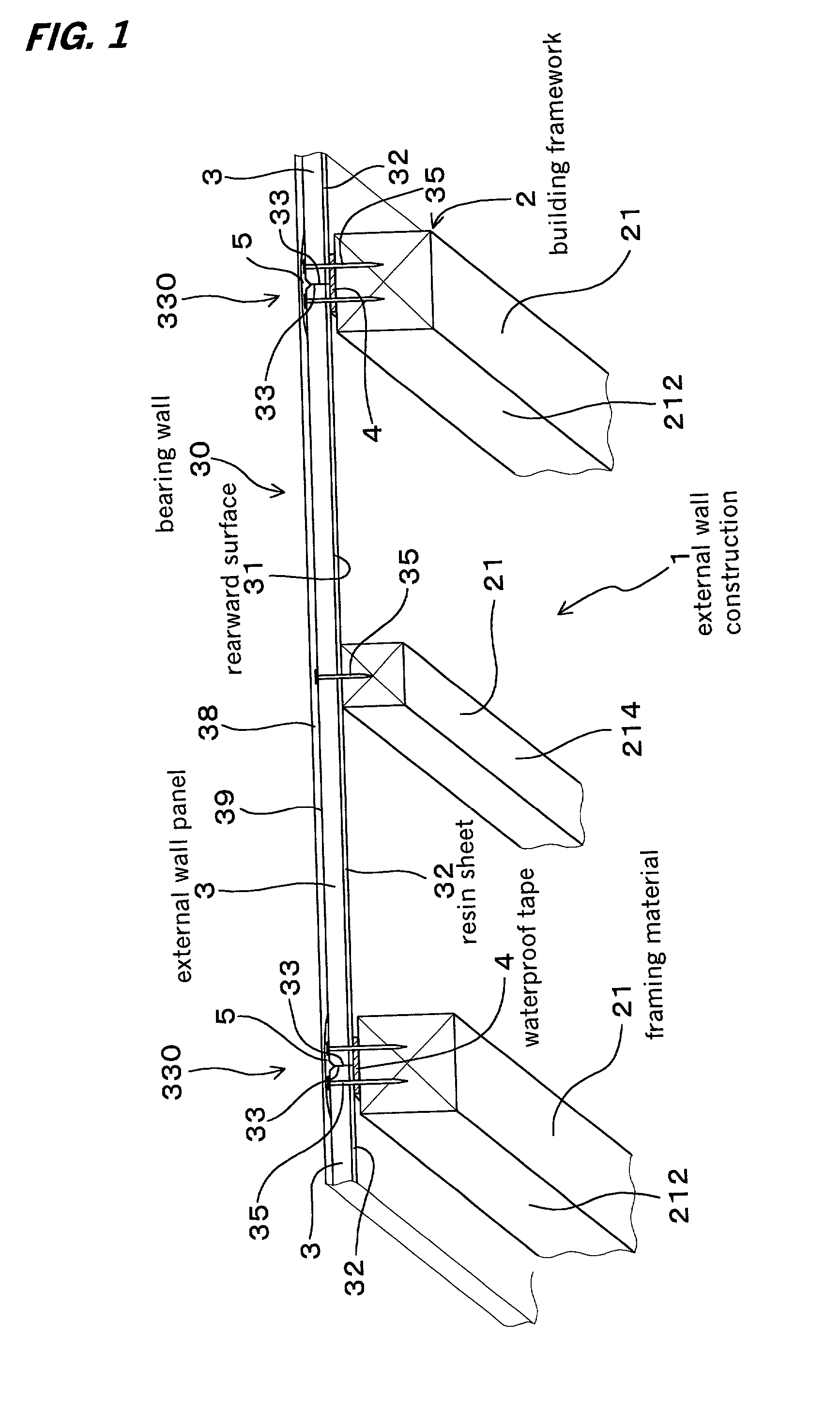
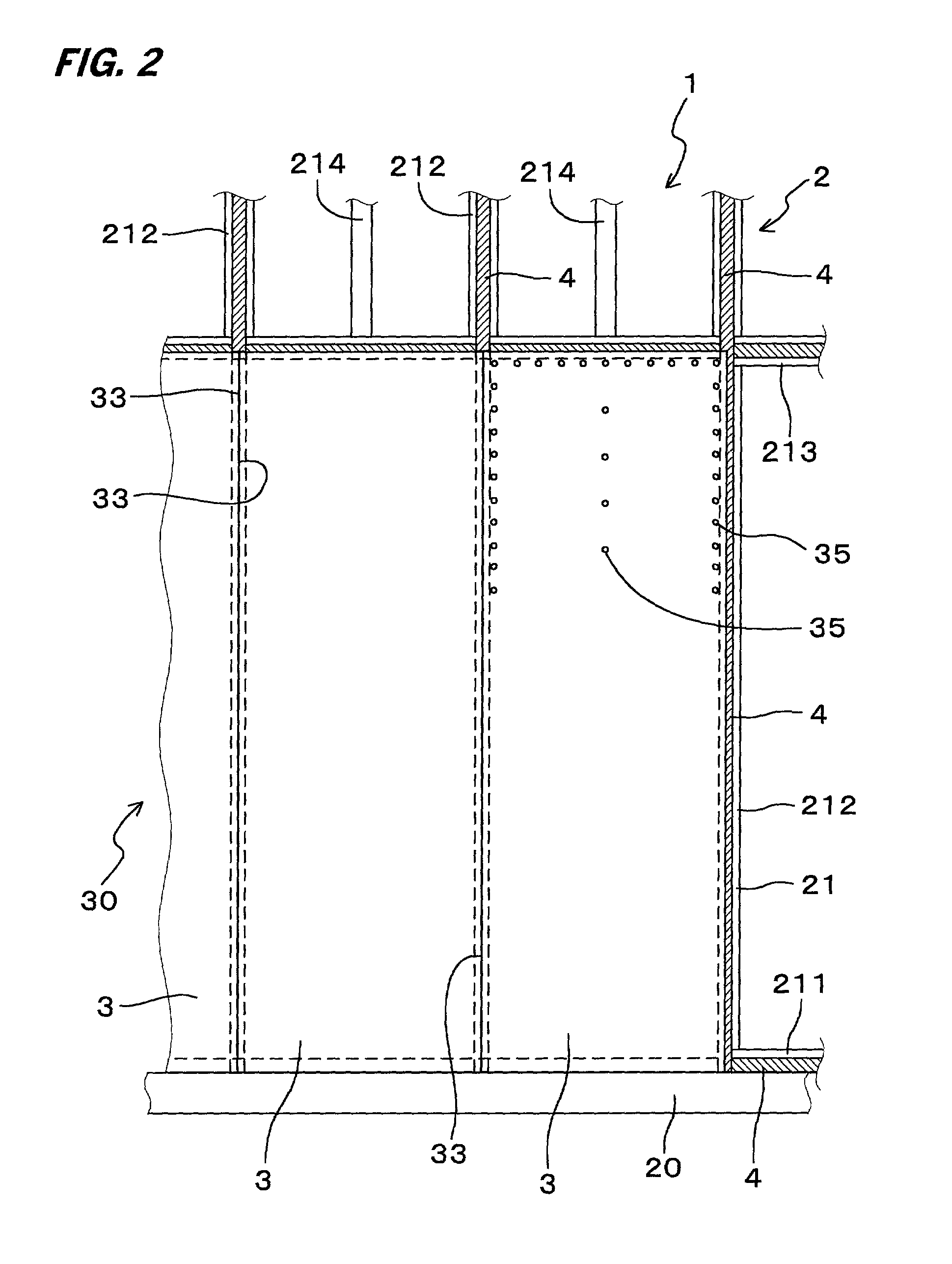
[0113] The external wall construction 1 according to the present embodiment as illustrated in FIGS. 1 and 2 is arranged as a bearing wall 30 comprised by fixing a plurality of ceramic type external wall panels 3 to a building framework 2 of a building.

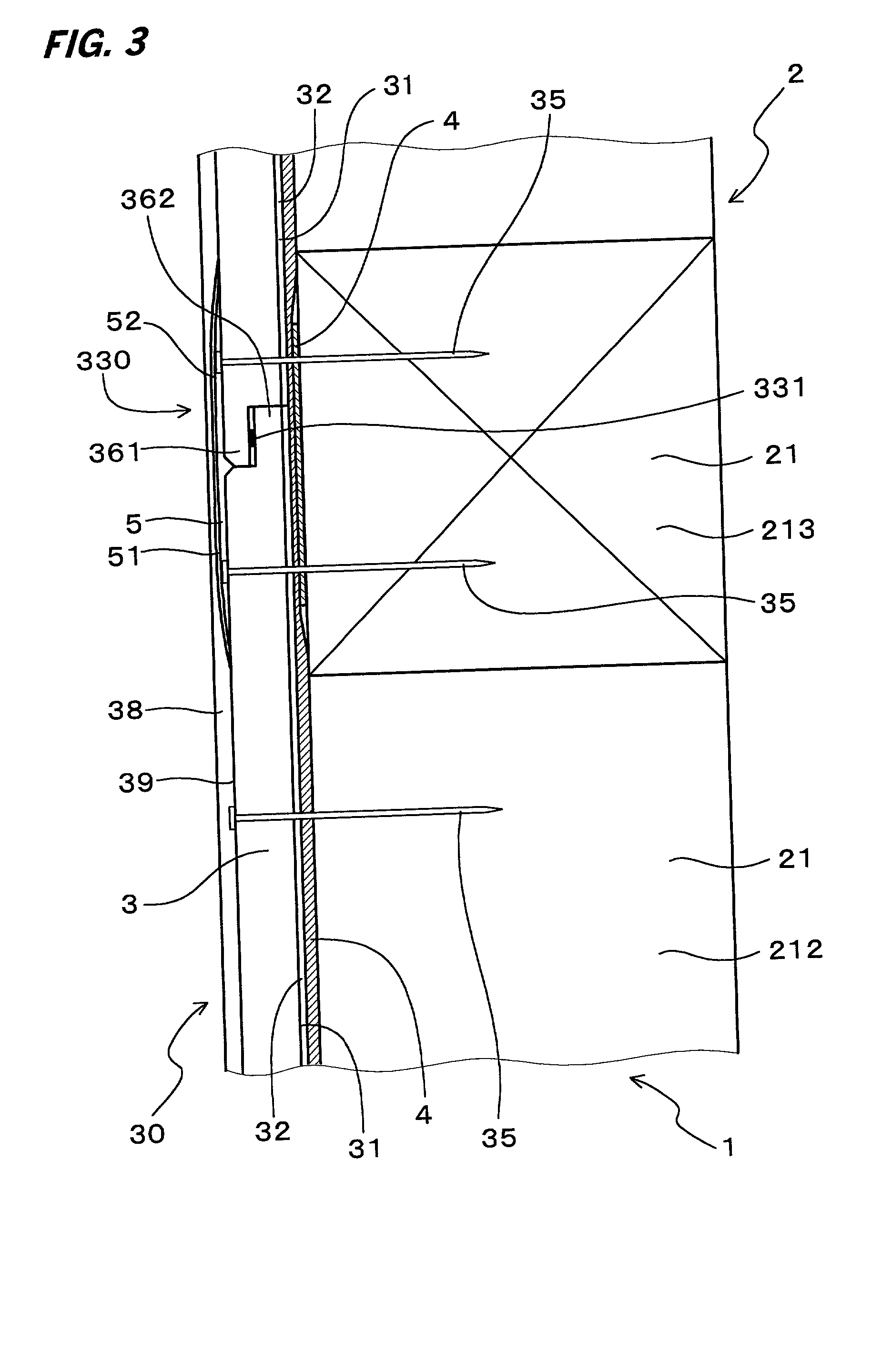
[0114] As illustrated in FIG. 4, a rearward surface 31 of each external wall panel 3 is backed with a resin sheet 32. Waterproof tapes 4 are further interposed between the external wall panels 3 and the building framework 2 as illustrated in FIGS. 1 and 2.

[0115] Hard chip cemented boards are employed as the external wall panels 3 and polyethylene sheets are employed as the resin sheets 32.

[0116] The building framework 2 is constructed of framing materials 21 made of timbers.

[0117] The resin sheets 32 are backed to the external wall panels 3 through fusion using a laminator.

[0118] The thickness of the ex...

embodiment 2

[0141] The present embodiment is an example employing foam polyethylene sheets 321 as the resin sheets 32 to be backed to the ceramic type external wall panels 3 as illustrated in FIG. 6.

[0142] The thickness of the resin sheets 32 is approximately 2.0 mm.

[0143] The remaining arrangements are identical to those of Embodiment 1.

[0144] The resin sheets 32 of this example have remarkable elasticity since the resin sheets 32 are foamed bodies (closed-cell structures) Thus, adhesion with the waterproof tapes 4 interposed between the building framework 2 and the external wall panels 3 may be performed in a more reliable manner.

[0145] Thus, it is possible to obtain an external wall construction of more superior waterproof properties.

[0146] The external wall construction of the present embodiment have extremely high resistance to impact applied through face-nailing so that cracks or chippings formed on rearward surfaces 31 of the external wall panels 3 can be more reliably prevented.

[0147] T...

embodiment 3

[0148] In this embodiment, the resin sheets 32 to be backed to the ceramic type external wall panels 3 are obtained by overlaying foam polyethylene sheets 321 and polyethylene terephthalate nonwoven cloths 322, as illustrated in FIG. 7.

[0149] More particularly, the foam polyethylene sheets 321 are backed to the rearward surfaces 31 of the external wall panels 3, whereon the polyethylene terephthalate nonwoven cloths 322 are backed as illustrated in FIG. 7.

[0150] The thickness of the resin sheets 32 is approximately 1.5 mm.

[0151] The remaining arrangements are identical to those of Embodiment 1.

[0152] In this arrangement, each resin sheet 32 comprises laminated foam layer and resin layer. Therefore, the mechanical strength of the sheets as backing materials is substantially improved.

[0153] Accordingly, it is possible to obtain an external wall construction having even superior waterproof properties and durability.

[0154] The present embodiment further have actions and effects identica...


PUM


Abstract

It is an object of the present invention to provide an external wall construction improving workability, waterproof properties, durability and ventilating properties of a bearing wall. The present invention relates to an external wall construction comprising a building framework of a building and a bearing wall constituted with a plurality of ceramic type external wall panels to be fixed to the building framework, wherein the external wall panels are formed by backing resin sheets on rearward surfaces thereof, and wherein waterproof tapes are interposed between the external wall panels and the building framework.

Description

[0001] 1. Field of the Invention[0002] The present invention relates to an external wall construction comprising a bearing wall constituted by fixing a plurality of ceramic type external wall panels to a building framework of a building through framework wall construction methods or skeleton framing wall construction methods.[0003] 2. Description of the Related Arts[0004] Conventional external wall constructions for building structural panels are known to be external wall constructions that are constructed through framework wall construction methods or skeleton framing wall construction methods.[0005] An example of such a conventional external wall construction 9 is illustrated in FIG. 19.[0006] This external wall construction 9 includes a building framework 92 constituted of framing materials 921 such as squared logs, building structural panels 93 fixed on the building framework 92, waterproof sheets 94 set on the building structural panel 93, lateral furring strips 95 fixed on the...

Claims


Application Information

Patent Timeline
IPC IPC(8): E04B1/70E04B2/70E04B2/90E04C2/04E04F13/00E04F13/04E04F13/06
CPCE04B1/7069E04B2/707E04F13/007E04F13/04E04F13/042
Inventor KANEKO, SHINICHIISHIKO, TAKUO
Owner NICHIHA CORP
Why Eureka
Try Eureka