

Single body injector and deposition chamber
a single-body injector and injector technology, applied in chemical vapor deposition coatings, coatings, metallic material coating processes, etc., can solve the problems of non-uniform film deposition, inability to properly operate semiconductors, and inability to uniform film composition, so as to reduce the number of components and seals, reduce maintenance and associated costs, and eliminate complicated machined parts
- Summary
- Abstract
- Description
- Claims
- Application Information
AI Technical Summary
Benefits of technology
Problems solved by technology
Method used
Image

Examples
second embodiment
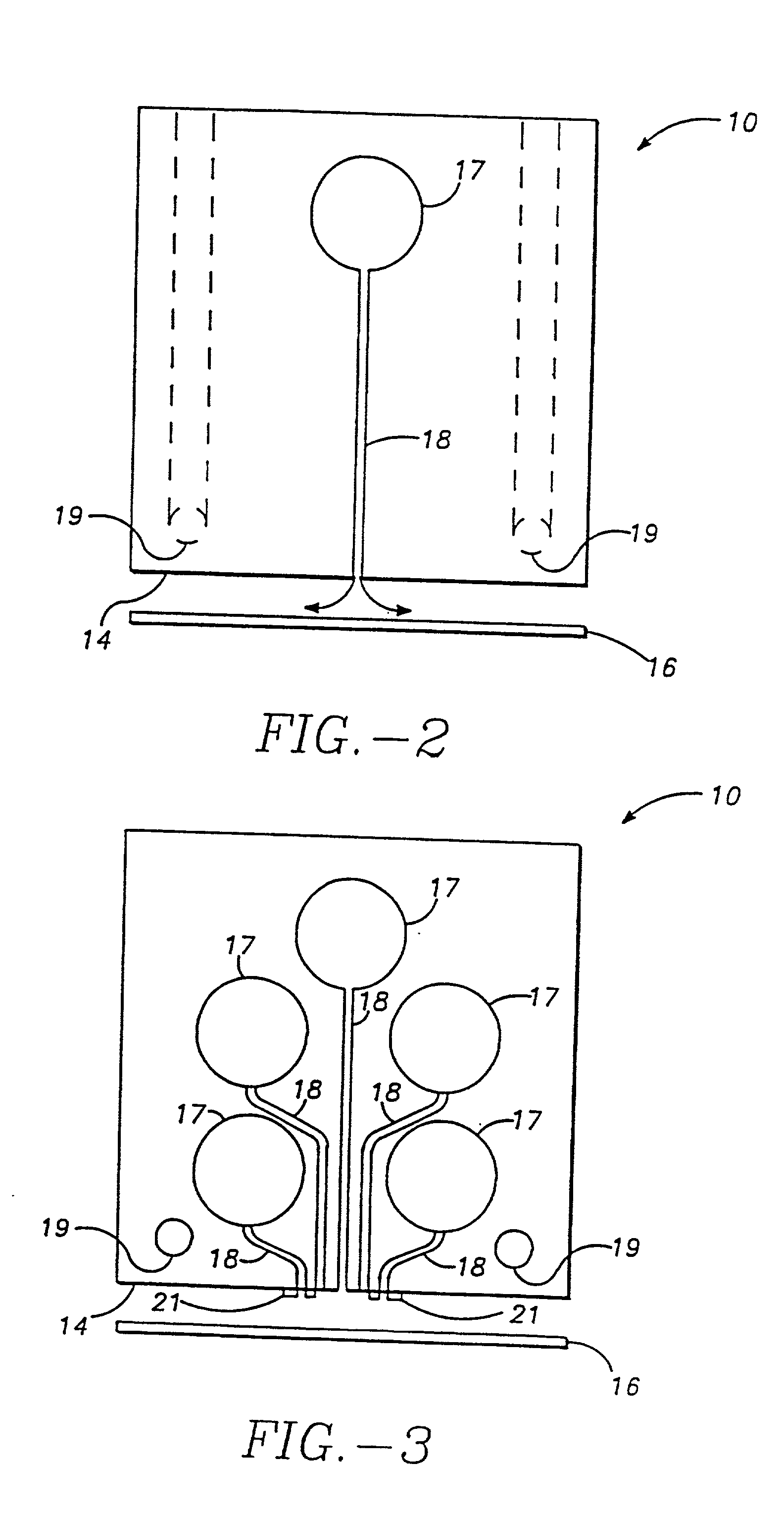
[0024] FIG. 3 is a cross-sectional view of an injector in accordance with the invention.
third embodiment
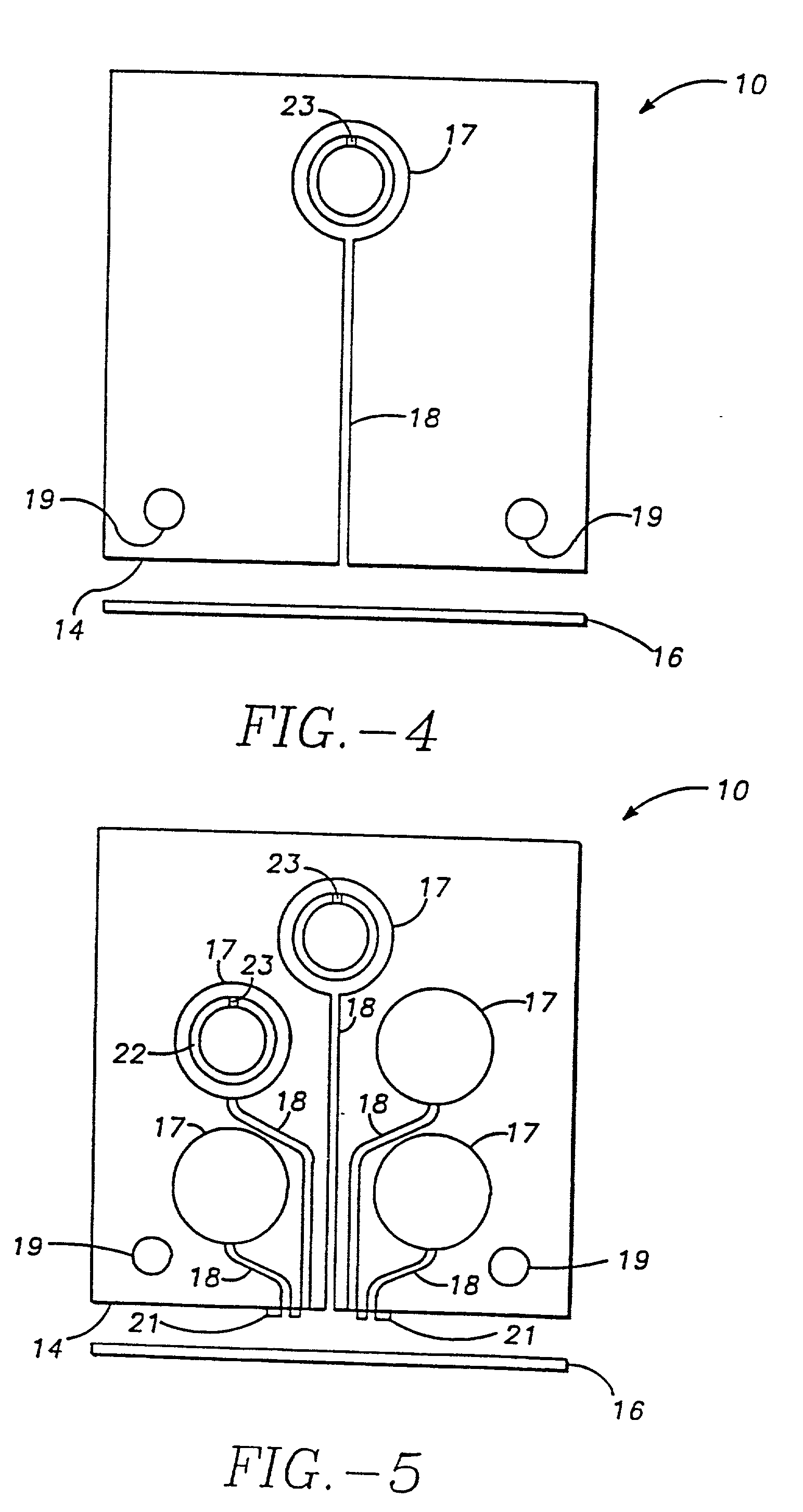
[0025] FIG. 4 is a cross-sectional view of an injector in accordance with the invention.
fourth embodiment
[0026] FIG. 5 is a cross-sectional view of an injector in accordance with this invention.
[0027] FIG. 6 is a cross-sectional view of the metering tube of the injector illustrated in FIGS. 4 and 5.
[0028] FIG. 7 illustrates a top plan view of one embodiment of an opening pattern in the metering tube of the injector-shown in FIGS. 4, 5 and 6.
[0029] FIG. 8 is a top plan view of an alternative opening pattern in the metering tube of the injector shown in FIGS. 4, 5 and 6.
[0030] FIG. 9 illustrates a top plan view of a slotted opening in the metering tube of the injector shown in FIGS. 4, 5, and 6.
[0031] FIG. 10 is a top plan view of another alternative opening pattern in the metering tube of the injector shown in FIGS. 4, 5 and 6.
[0032] FIG. 11 is a top plan view of yet another alternative opening pattern in the metering tube of the injector shown in FIG. 4, 5 and 6.
[0033] FIG. 12 illustrates an enlarged partial side view of the flange and metering tube attachment to the injector.
[0034] FI...
PUM
| Property | Measurement | Unit |
|---|---|---|
| distance | aaaaa | aaaaa |
| distance | aaaaa | aaaaa |
| diffusion length | aaaaa | aaaaa |
Abstract
Description
Claims
Application Information