Process for coating a ceramic honeycomb body

a honeycomb body and ceramic technology, applied in the direction of catalyst activation/preparation, metal/metal-oxide/metal-hydroxide catalysts, machines/engines, etc., can solve the problem of premature solidification of the suspension in the flow channel, the possibility of obstruction of the flow channel of the high-cell honeycomb body with excess coating material, and the increase of the obstruction of the flow channel of the high-cell honeycomb body

Inactive Publication Date: 2001-07-05
UMICORE AG & CO KG +1
View PDF0 Cites 19 Cited by
  • Summary
  • Abstract
  • Description
  • Claims
  • Application Information

AI Technical Summary

Problems solved by technology

A substantial problem with coating is the possible obstruction of the flow channels with excess coating material as a result of the suction capacity of the porous ceramic honeycomb bodies for the liquid phase of the coating suspension, and the consequent premature solidification of the suspension in the flow channels.
Because of the small channel cross-sections, these high-cell honeycomb bodies tend to suffer from increased obstruction of the flow channels during coating.
However, compared with an unwetted honeycomb body, this causes an undesirable reduction in the achievable coating concentration when using an already highly concentrated coating suspension.
Coating of honeycomb bodies with the coating suspension is accompanied by the danger, already described, of obstruction of the flow channels by coating material, obstructed channels being observed principally in the marginal region of the honeycomb bodies.

Method used


Image

  • Process for coating a ceramic honeycomb body
  • Process for coating a ceramic honeycomb body

Examples


Embodiment Construction

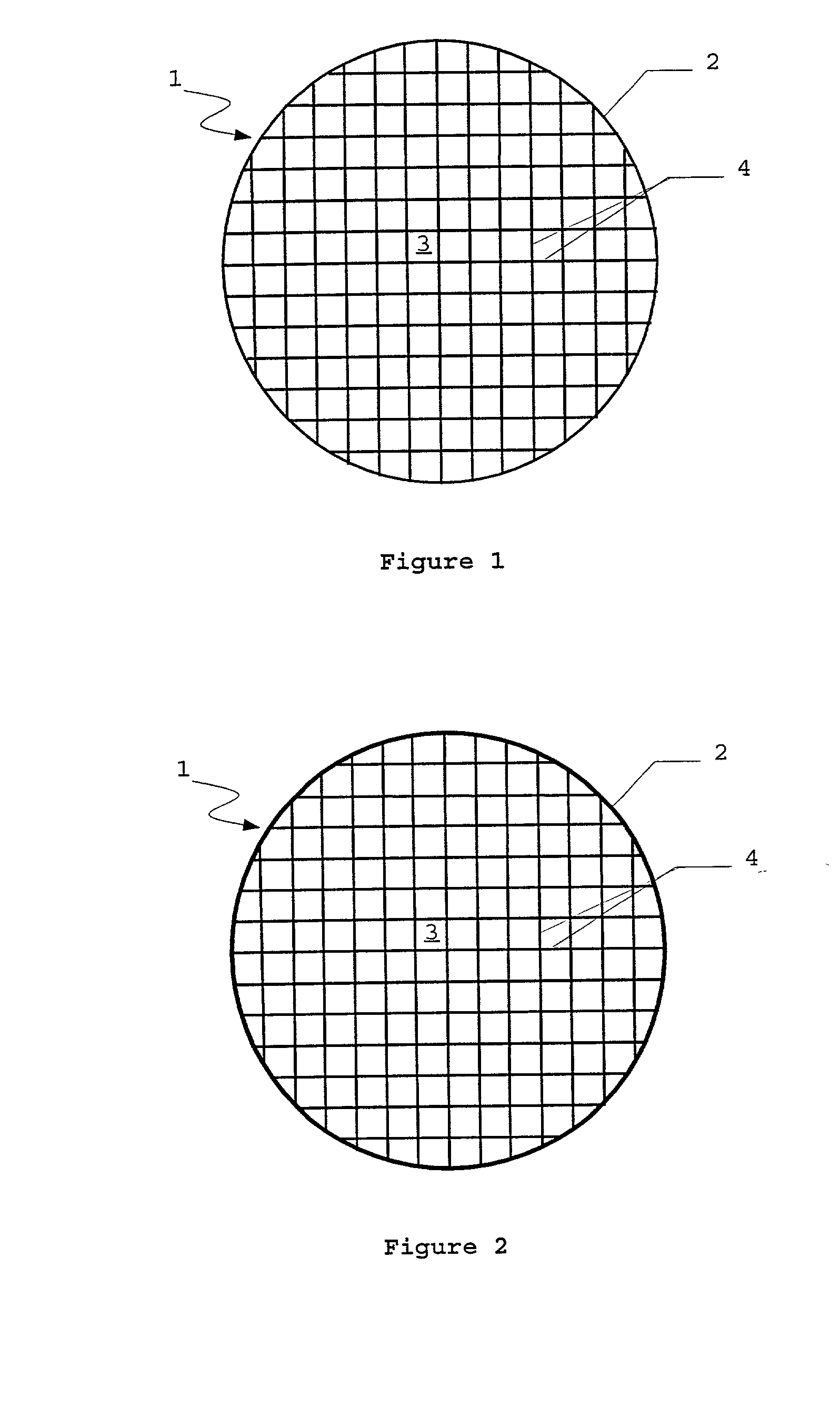
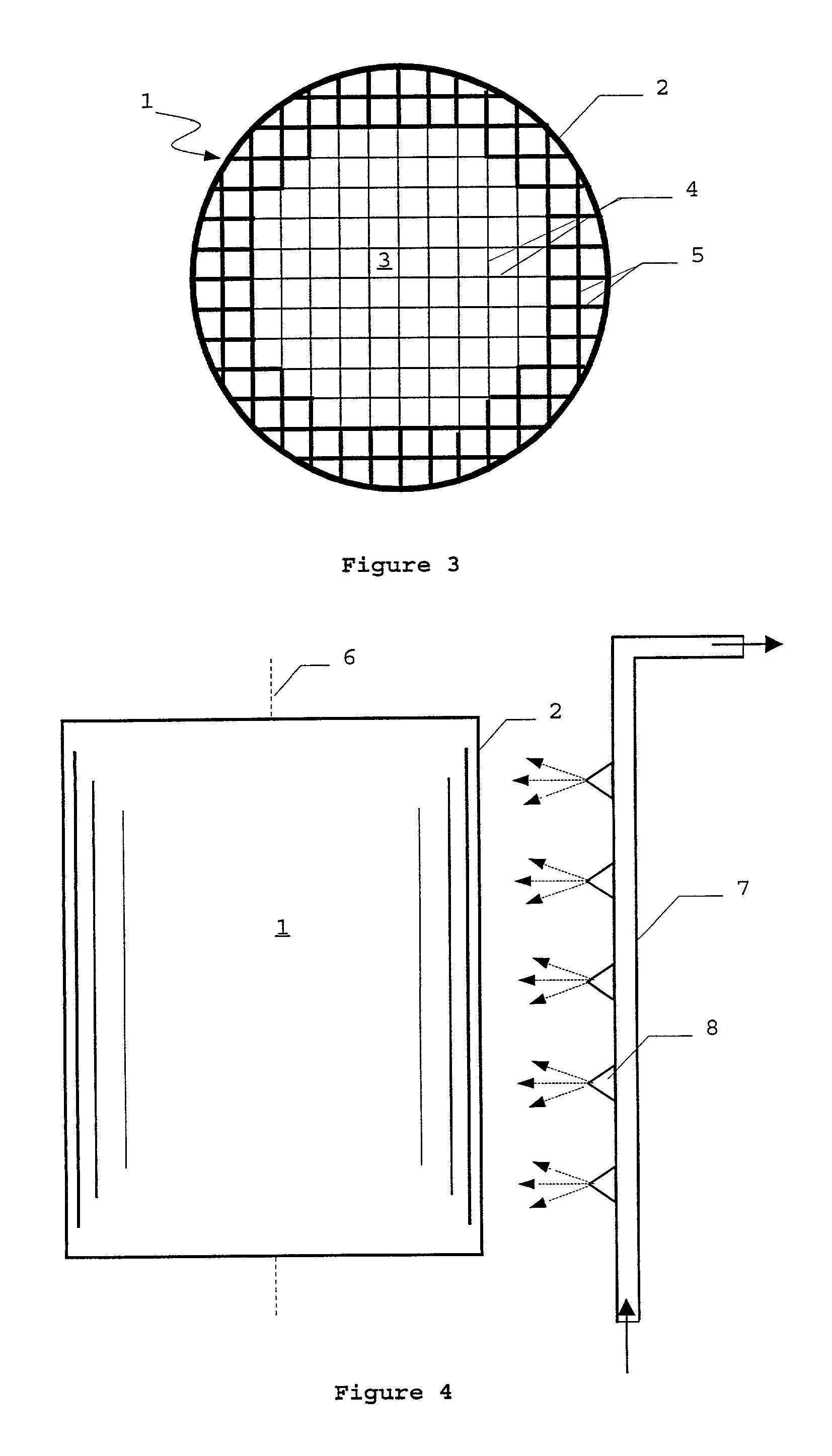
[0024] According to the invention, the suction capacity in the region of the jacket of the honeycomb bodies is at least partially saturated, prior to coating, by wetting the jacket of the honeycomb body. In this embodiment of the process, in contrast to DE 198 10 260 A1, only the jacket of the honeycomb body, and not the entire honeycomb body, is wetted. Whereas according to DE 198 10 260 A1 the coating concentration is reduced in all the flow channels by uniform wetting of the entire honeycomb body, in the proposed process this is only the case in the marginal region. In this way high coating concentrations can be obtained by means of only one coating operation, with a simultaneous reduction in the number of obstructed channels in the marginal region.

[0025] The degree of saturation and the depth of penetration of the wetting can be controlled by those skilled in the art by means of the liquid volume used and optionally by introducing a waiting time between wetting and coating. This...


PUM

PropertyMeasurementUnit
concentrationaaaaaaaaaa
thicknessaaaaaaaaaa

Abstract

A process for coating, with a suspension, a ceramic honeycomb body which has a cylindrical shape with two flat end-faces and one jacket, and through which channels parallel to the axis, formed by channel walls, run from one flat end-face to the other, the honeycomb body being coated by suitable processes. The honeycomb body is partially wetted and then coated.

Description

INTRODUCTION AND BACKGROUND[0001] The present invention relates to a process for coating a ceramic honeycomb body with a suspension.[0002] Ceramic bodies in the form of honeycombs are used in large numbers in the field of catalysis -especially in the field of the catalytic purification of motor vehicle exhaust gases-as carriers for catalytically active coatings. The carriers have a generally cylindrical shape and are delimited by two flat end-faces and one jacket. Channels parallel to the axis, or flow channels, through which the exhaust gas to be purified is passed, run through said carriers from one flat end-face to the other. Such carriers are also referred to as honeycomb bodies.[0003] The catalyst for converting the pollutants present in the exhaust gas (mainly hydrocarbons, carbon monoxide and nitrogen oxides) generally consists of pulverulent materials of large surface area onto which the actual catalytically active components are deposited in highly disperse form. This catal...

Claims


Application Information

Patent Timeline
Patent Type & Authority Applications(United States)
IPC IPC(8): B01J19/00B01J35/04B01J37/02B05D7/00B01D53/86C04B38/00C04B41/52C04B41/85C04B41/87F01N3/28
CPCB01J35/04B01J37/0217C04B41/009C04B41/52C04B2111/0081C04B2111/00844F01N3/2828F01N2260/18C04B41/502C04B41/4539C04B41/457C04B41/50C04B38/0006Y10S55/30Y10T428/24149
Inventor DOMESLE, RAINERKREUZER, THOMASLOX, EGBERT
Owner UMICORE AG & CO KG
Why Eureka
Try Eureka