Traverse linearity compensation method and rotational accuracy compensation method of measuring device

a compensation method and measurement device technology, applied in measurement devices, speed/acceleration/shock measurement devices, instruments, etc., can solve problems such as high difficulty and skill requirements for correct setting of workpieces during measurement, and a large number of steps, and the reliability of [method 1] is not so high

a compensation method and measurement device technology, applied in measurement devices, speed/acceleration/shock measurement devices, instruments, etc., can solve problems such as high difficulty and skill requirements for correct setting of workpieces during measurement, and a large number of steps, and the reliability of [method 1] is not so high

US20010008047A1Inactive Publication Date: 2001-07-19MITUTOYO CORP

Image

  • Traverse linearity compensation method and rotational accuracy compensation method of measuring device
  • Traverse linearity compensation method and rotational accuracy compensation method of measuring device
  • Traverse linearity compensation method and rotational accuracy compensation method of measuring device

Examples


first embodiment

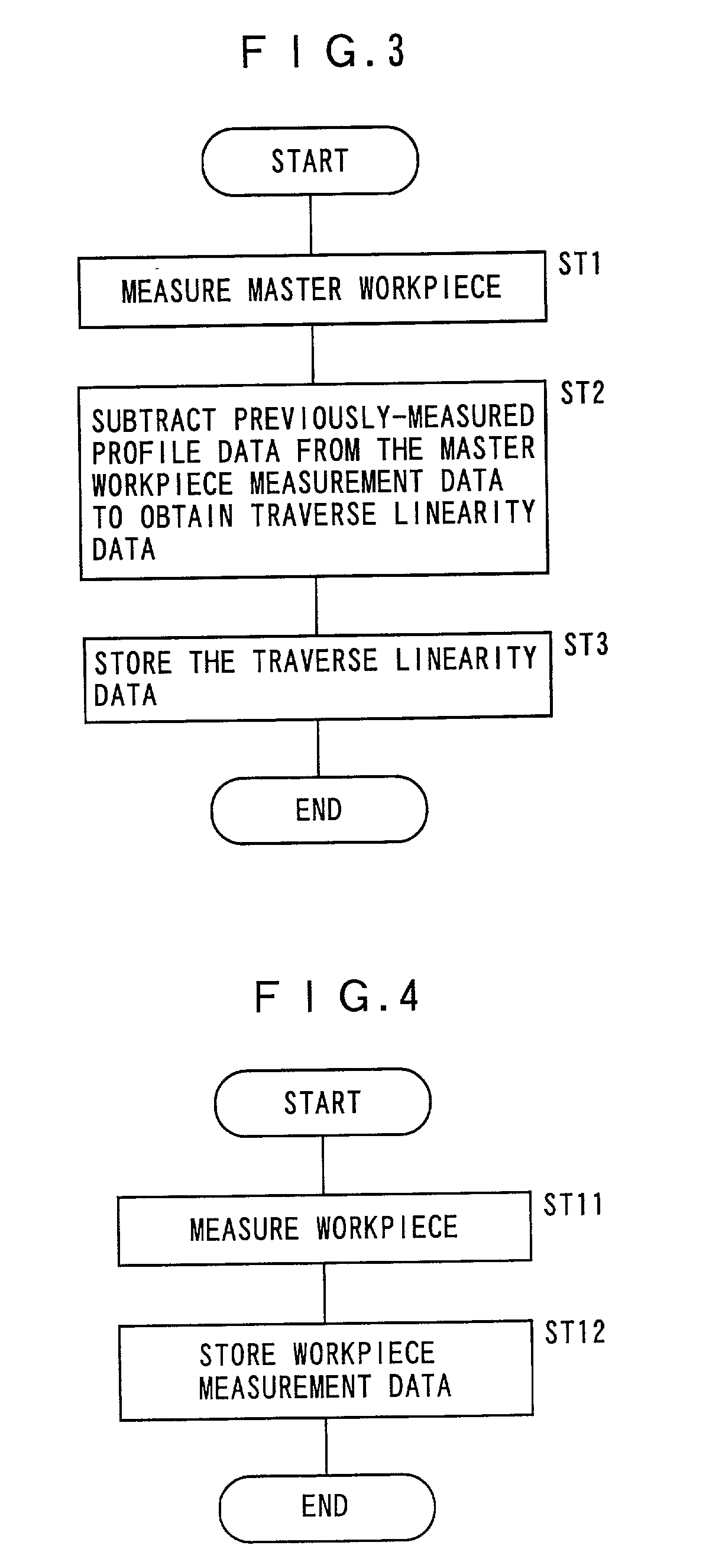
[0052] [First Embodiment]

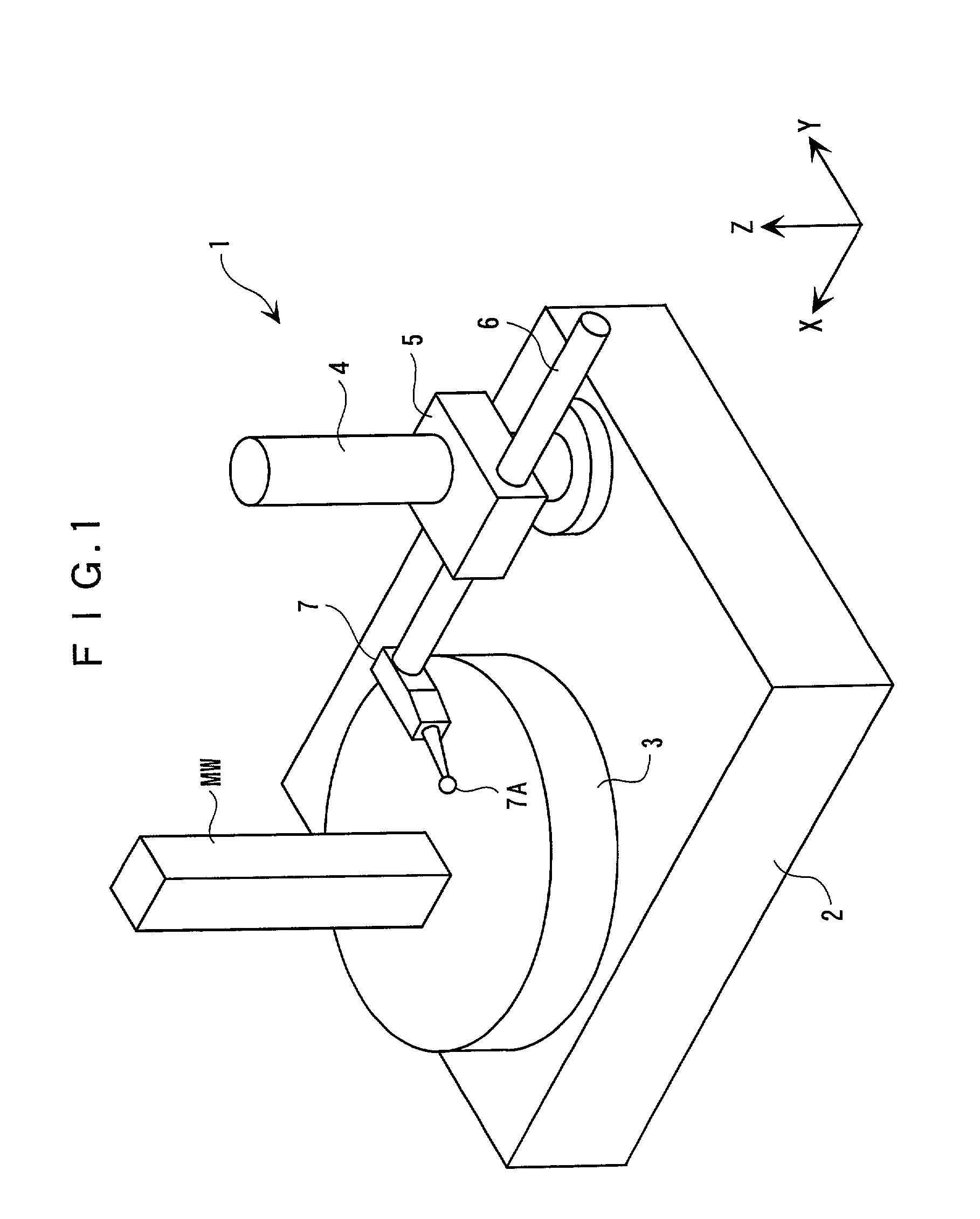
[0053] FIGS. 1 to 7 show a first embodiment of the present invention.

[0054] The present embodiment is an example of applying the present invention to a traverse linearity compensation method of a roundness measuring device.

[0055] FIG. 1 shows a roundness measuring device 1 of the present embodiment. The roundness measuring device 1 has a base 2, a rotary table 3 rotatably disposed around a perpendicular axis (Z-axis) on an upper side (left side in the figure) of the base 2, a column 4 disposed parallel to the Z-axis on the upper surface of the base 2 (on the right side in the figure), a slider 5 provided vertically movably (in Z-axis direction) along the column 4, an arm 6 provided to the slider 5 being advanceable and retractable in a direction orthogonal with the column 4 (X-axis direction), and a sensor 7 attached to a distal end of the arm 6 to be position-adjustable in Y-axis direction and having a probe 7A at a distal end thereof.

[0056] Incidentally, a...

second embodiment

[0104] [Second Embodiment]

[0105] FIGS. 10 to 13 show a second embodiment of the present invention.

[0106] The present embodiment is an application of the present invention to a rotational accuracy compensation method of a roundness measuring device.

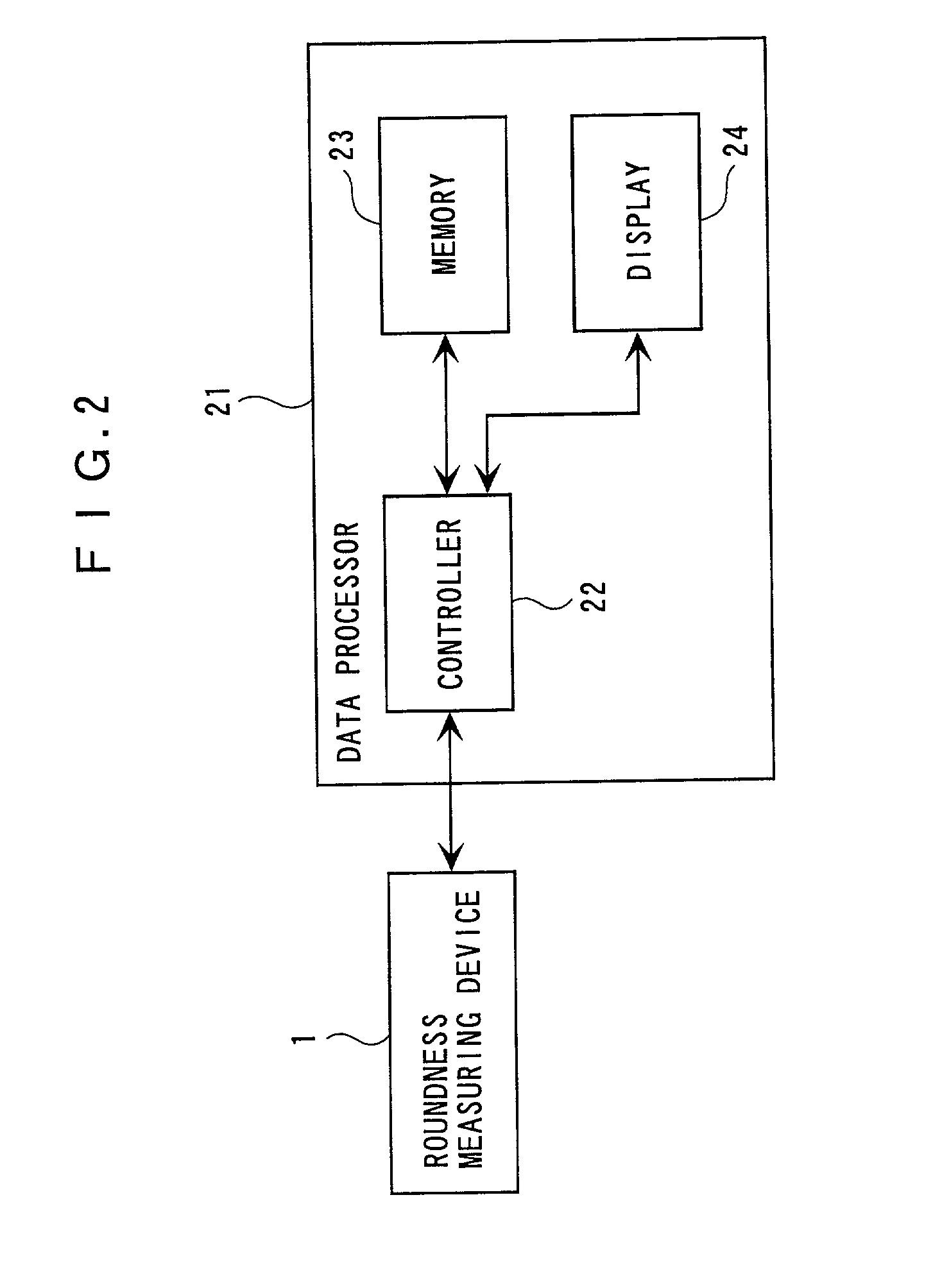
[0107] FIG. 10 shows a roundness measuring device 1 according to the present embodiment. The roundness measuring device 1 is the same as the roundness measuring device 1 of the above-described first embodiment and detailed explanation of specific components is omitted herein.

[0108] In the present embodiment, a workpiece (not shown) is put on the rotary table 3 and the master workpiece MW is rested through a measurement jig 11.

[0109] The measurement jig 11 has a short-cylindrical mount 12 having a master workpiece MW on an upper surface 13 thereof, and a reference ball 15 buried and half-exposed on the periphery of the mount 12. The outer diameter of the mount 12 and the master workpiece MW are concentric. The master workpiece MW is formed ...


PUM


Abstract

A compensation method according to the present invention includes: a traverse linearity data calculating step for measuring a master workpiece (MW) of which profile data is value-specified in advance while moving a sensor (7) using a linear movement mechanism (4, 5) of a measuring device (1) and for subtracting the previously value-specified profile data from the measurement data of the master workpiece to obtain a traverse linearity data of the linear movement mechanism; a workpiece measurement data calculating step for measuring the workpiece while moving the sensor by the linear movement mechanism of the measuring device to obtain a measurement data of the workpiece; and a workpiece profile calculating step for subtracting the traverse linearity data from the workpiece measurement data to obtain a true value data of the workpiece.

Description

[0001] 1. Field of the Invention[0002] The present invention relates to a traverse linearity compensation method and a rotational accuracy compensation method of a measuring device. More specifically, it relates to a traverse linearity compensation method of a measuring device having a linear movement mechanism, such as a roundness-measuring device and a roughness-measuring device, for compensating traverse linearity of the linear movement mechanism. It also relates to a rotational accuracy compensation method of a measuring device having a rotary mechanism such as a roundness-measuring device for compensating a rotational accuracy of the rotation mechanism.[0003] 2. Description of Related Art[0004] When a workpiece is measured by a measuring device having a linear movement mechanism as a guide (reference) such as a roundness-measuring device and a roughness-measuring device, the resulted measurement data is a composition of a profile data of the workpiece and a mechanical accuracy ...

Claims


Application Information

Patent Timeline
19 Jul 2001
Publication
US20010008047A1
IPC
G01B5/008
CPC
G01B5/008; G01B21/042; G01B21/045; G01B5/201
Inventors
OKADA, EIJI; OMORI, YOSHIYUKI