Underground information communication system and related manhole cover

Inactive Publication Date: 2001-08-02
MITSUBISHI ELECTRIC CORP +2
View PDF0 Cites 42 Cited by
  • Summary
  • Abstract
  • Description
  • Claims
  • Application Information

AI Technical Summary

Problems solved by technology

However, conventional information communication systems such as the above system using a manhole cover as a communication base station experience problems when carrying out maintenance for the sewer because the manhole cover is direc

Method used


Image

  • Underground information communication system and related manhole cover
  • Underground information communication system and related manhole cover
  • Underground information communication system and related manhole cover

Examples


embodiment 2

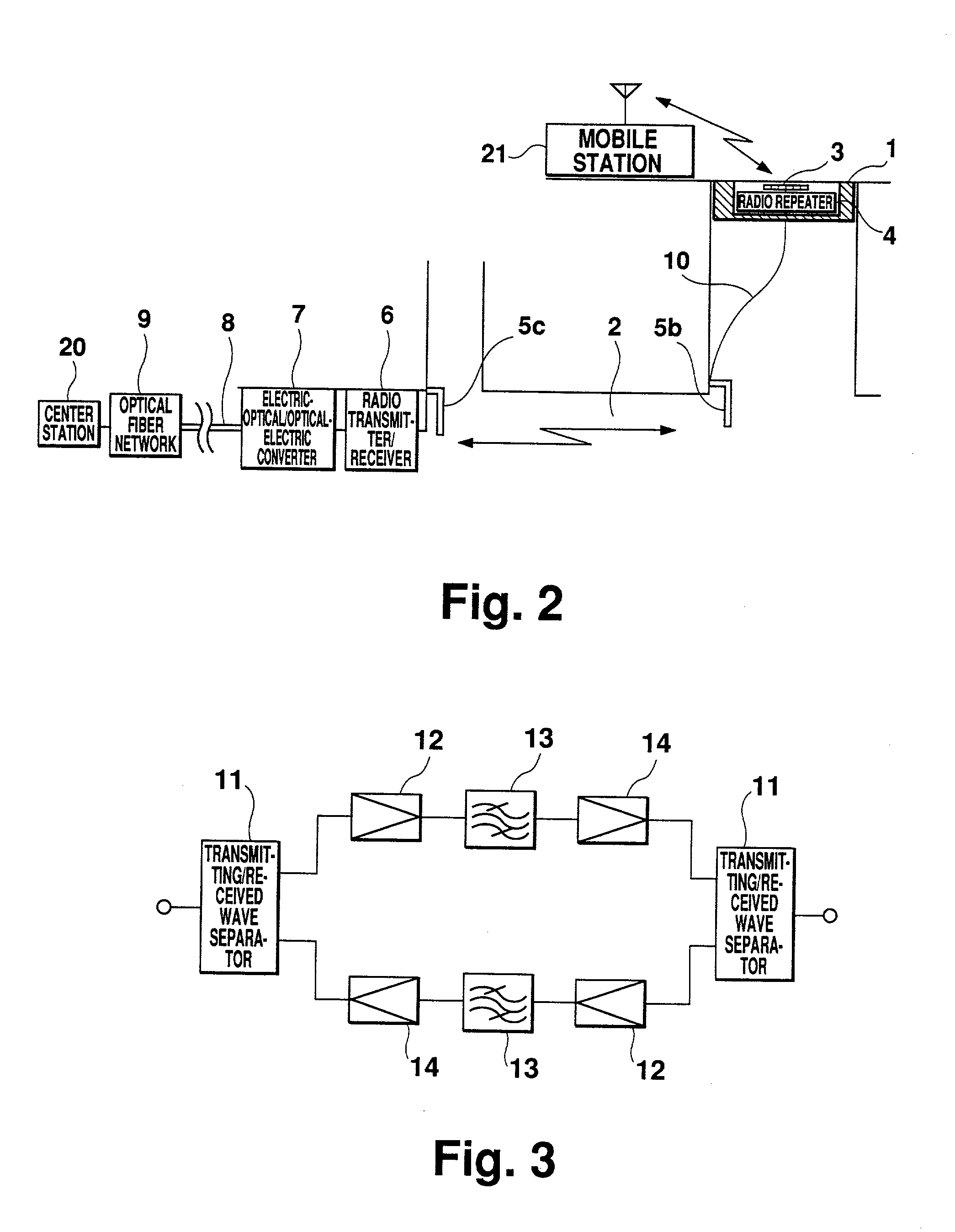
[0028] FIG. 2 shows an information communication system of a second embodiment of the present invention. This drawing includes a co-axial cable 10 in addition to the same elements with the same reference numerals as those in embodiment 1.

[0029] In this embodiment 2, a radio repeater antenna 5 is provided inside a sewer. As shown in FIG. 2, the radio repeater antenna is disposed at an intersection of a main sewer (horizontally extending) and the brand sewer (manhole). Radio electric waves transmitted from a radio repeater antenna 5b provided on the manhole cover 1 side is transmitted along the horizontally extending sewer to be received by a radio repeater antenna 5c provided on the optical fiber side which is located in a main sewer. In sewerage, with a diameter generally between 20 cm to 8 m, radio electric waves having a higher frequency than a cut-off frequency expressed in equation 1 are transmitted.

f.sub.c=C / 3.413a (equation 1)

[0030] wherein f.sub.c is a cut-off frequency (Hz),...

embodiment 3

[0032] FIG. 3 shows the structure of a radio repeater 4 of this invention. This drawing includes a transmitting / received wave separator 11, a low noise amplifier 12, a band pass filter (BPF) 13, and a high output amplifier 14. Separator 11 separates transmitting signals and received signals. Received signals are amplified by low noise amplifier 12 and filtered by BPF 13 so that only signals in a predetermined frequency band are passed through the filter. The signals obtained in a predetermined frequency band are amplified by high output amplifier 14, and then transmitted via separator 11.

[0033] A radio repeater 4 generally has a problem of an oscillation of the circuit because the antennas each connecting to each end of the radio repeater 4 are located close to each other are coupled to each other, so various countermeasures for avoiding the coupling of the antennas are thus employed. In this invention, a manhole cover antenna 3 is located sufficiently away from a radio repeater ant...

embodiment 4

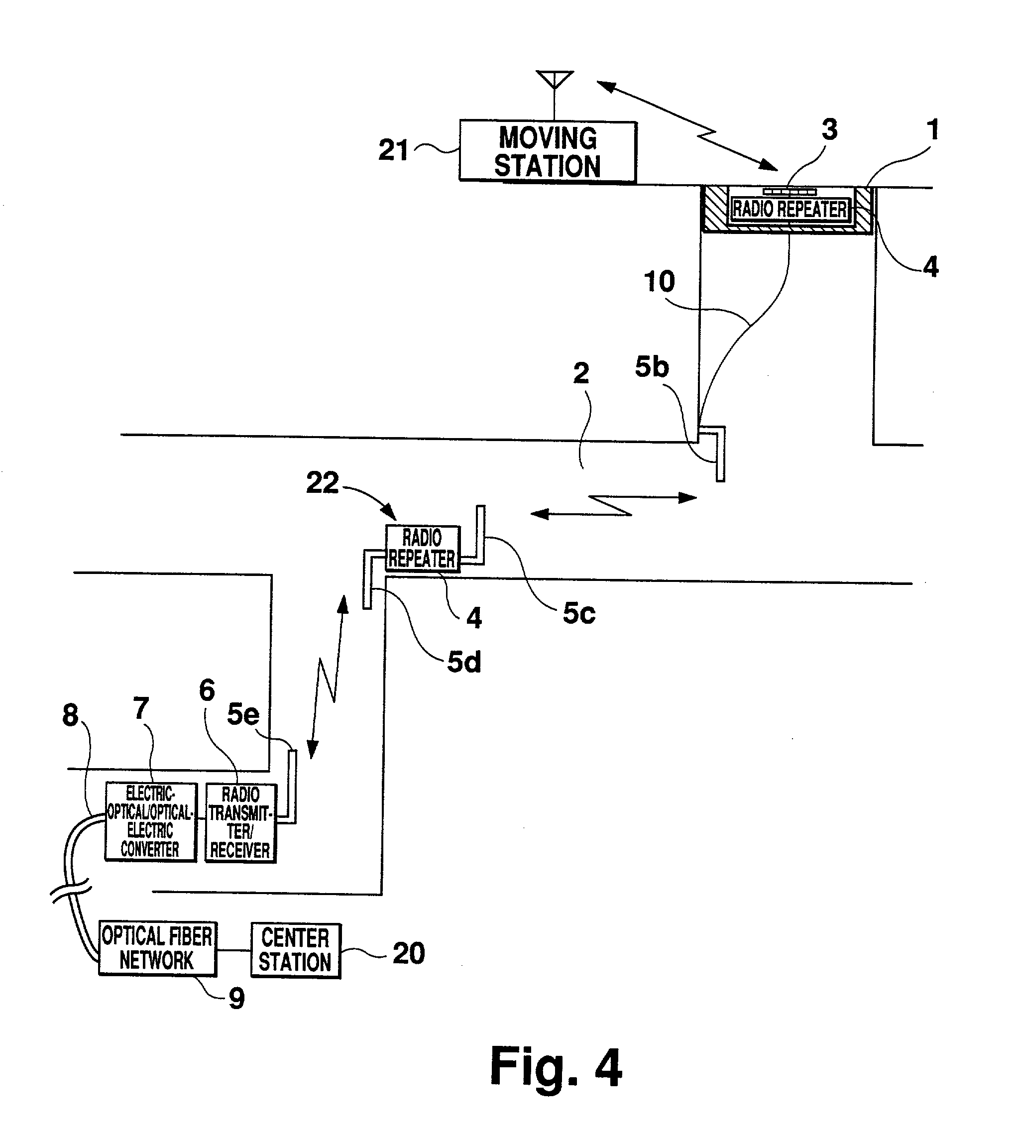
[0034] FIG. 4 shows an information communication system of a fourth embodiment of the present invention. In this drawing, respective reference numerals are the same as those used in the second embodiment.

[0035] In this embodiment, a transmission repeater device 22 which comprises at least one pair of radio repeater antennas 5c and 5d and a radio repeater 4 is provided between radio repeater antenna 5b below manhole cover 1 and a radio repeater antenna 5e on the optical fiber cable 8 side. Even in cases where radio transmission is employed in connecting between antennas in a sewer, a transmissible distance is still subject to limitations. That is, it is difficult to receive sufficient power in a long distance transmission. Even in a short distance, transmitting power is remarkably attenuated while passing through an angled or branching sewer. This invention, however, is free from the above problems since a communication repeater device 22 is disposed at branches and such midpoints of...


PUM


Abstract

A manhole cover is provided with an incorporated radio repeater and a repeater antenna attached onto its rear surface. Another repeater antenna is provided inside the sewer below the manhole. This repeater antenna is connected to a radio transmitter/receiver, an electric-optical/optical-electric signal converter, and an optical fiber cable. With this arrangement, the manhole cover and optical fiber cable are connected via radio communication.

Description

[0001] 1. Field of the Invention[0002] This invention relates to an information communication system using manhole covers as communication base stations.[0003] 2. Description of the Related Art[0004] FIG. 6 illustrates a manhole antenna device and an information communication system disclosed in Japanese Patent Laid-Open No. Hei 5-227073. The drawing includes a manhole cover 1, a sewer 2, an antenna 3 incorporated into manhole cover 1, a radio transmitter / receiver 6, an electric-optical / optical-electric signal converter 7, an optical fiber cable 8, an optical fiber network 9, and a center station 20.[0005] In operation, when signals are transmitted from center station 20, center station 20 outputs information signals into optical fiber network 9 via optical fiber cable 8. The signals are transmitted through optical-electric signal converter 7 and radio transmitter / receiver 6, and then they are irradiated towards the outside of a manhole in the form of radio electric waves via manhol...

Claims


Application Information

Patent Timeline
IPC IPC(8): H01Q1/44E02D29/14G02B6/44
CPCE02D29/14G02B6/4451G02B6/447H04B10/25752E02D29/1481G02B6/501G02B6/562
Inventor HARADA, TOSHIOSHIMIZU, YOJICHATANI, YOSHIYUKIFURUNO, TAKAYOSHI
Owner MITSUBISHI ELECTRIC CORP
Why Eureka
Try Eureka