
Signal encoding transmission apparatus, signal decoding receiving apparatus, and program recording medium

a technology of signal encoding and transmission apparatus, applied in multi-frequency code systems, multiplex communication, orthogonal multiplex, etc., can solve problems such as the inability to reconstruct video signals in total

Inactive Publication Date: 2001-08-09
PANASONIC CORP
View PDF3 Cites 127 Cited by
  • Summary
  • Abstract
  • Description
  • Claims
  • Application Information

AI Technical Summary

Problems solved by technology

The prior art thus has had the problem that, under poor reception conditions (for example, in the case of mobile communications), since all the carrier signals cannot be received correctly, there frequently arises the situation where the video signal cannot be decoded, resulting in a total inability to reconstruct the video signal.

Method used


Image

  • Signal encoding transmission apparatus, signal decoding receiving apparatus, and program recording medium
  • Signal encoding transmission apparatus, signal decoding receiving apparatus, and program recording medium
  • Signal encoding transmission apparatus, signal decoding receiving apparatus, and program recording medium

Examples


embodiment 1

[0080] (Embodiment 1)

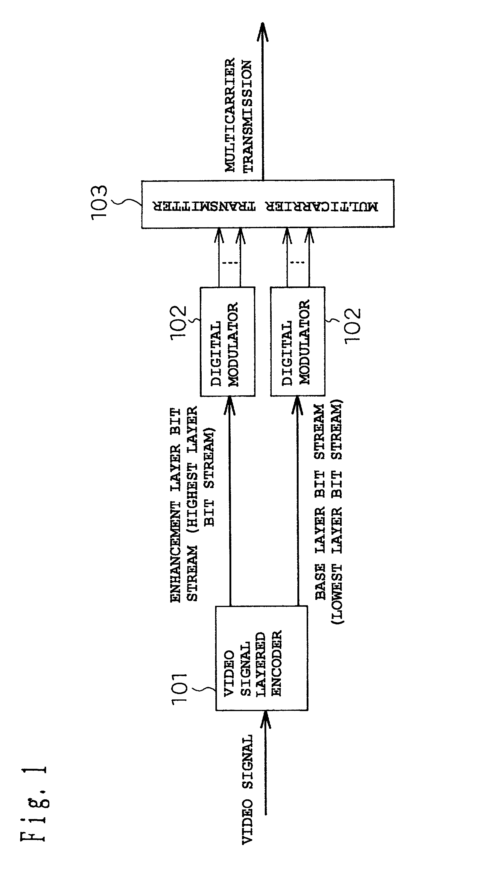
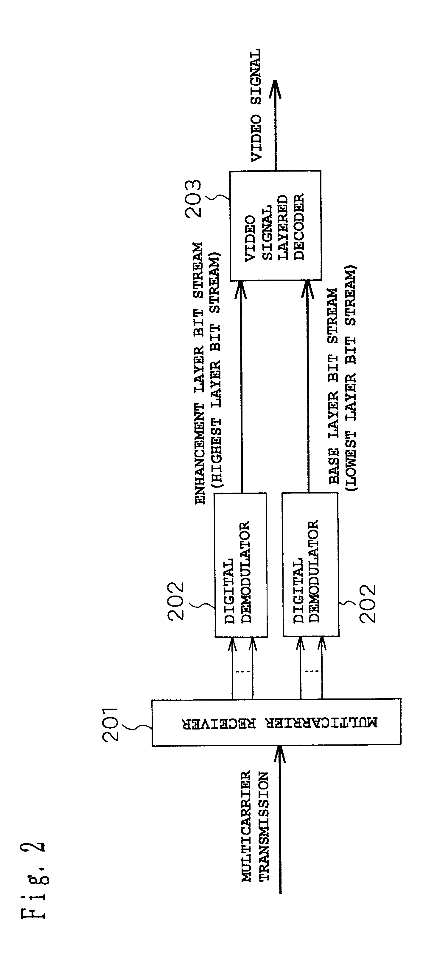
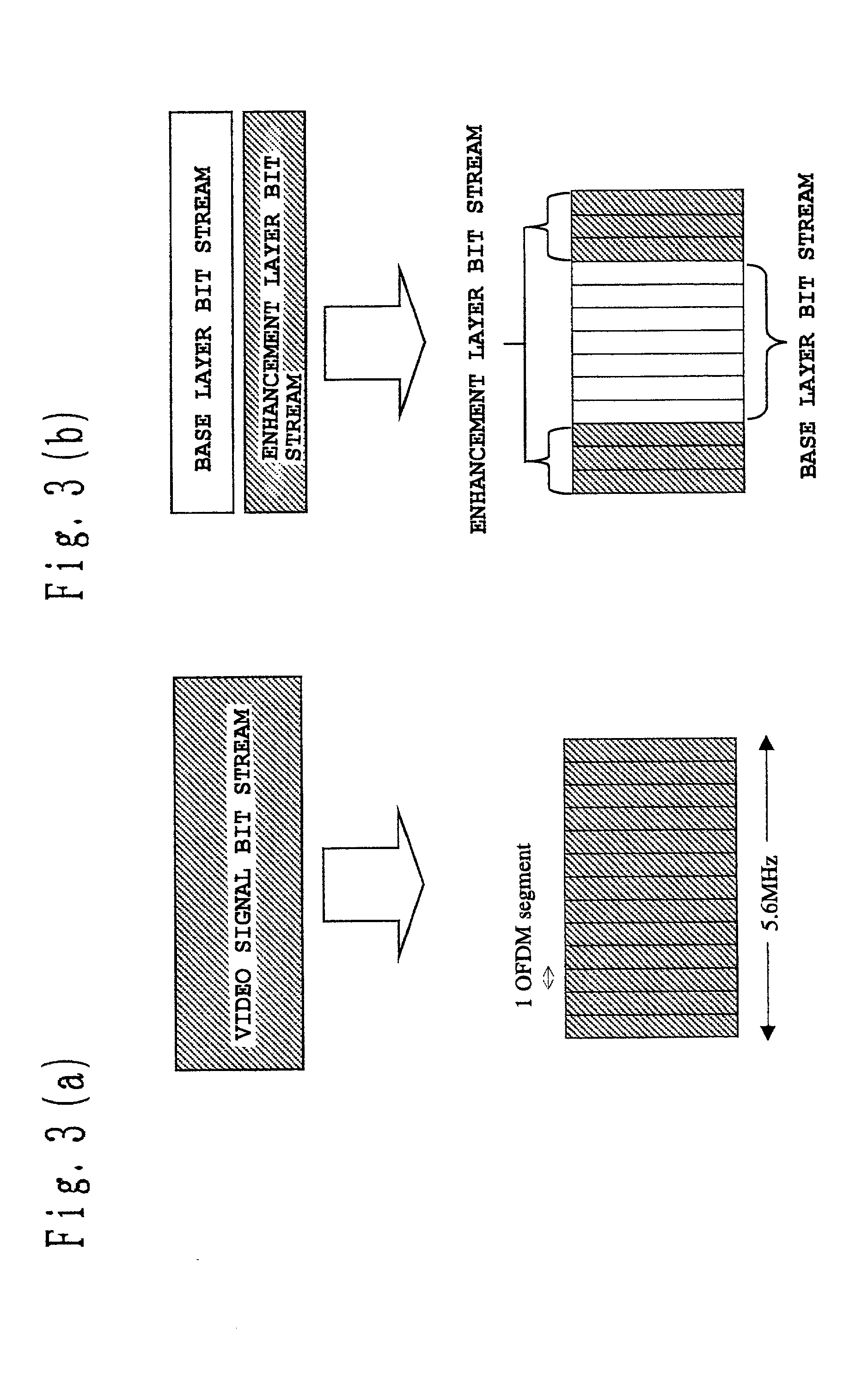
[0081] The configuration and operation of a signal encoding transmission apparatus and a signal decoding receiving apparatus according to a first embodiment will be described below by referring primarily to FIGS. 1 to 3.

[0082] First, the configuration and operation of the signal encoding transmission apparatus according to the first embodiment will be described by referring primarily to FIG. 1.

[0083] In FIG. 1, reference numeral 101 is a video signal layered encoder, 102 is a digital modulator, and 103 is a multicarrier transmitter.

[0084] The video signal layered encoder 101 in the first embodiment corresponds to the layered encoding means of the present invention. The digital modulator 102 and the multicarrier transmitter 103 in the first embodiment together constitute the modulating / transmitting means of the present invention.

[0085] The video signal layered encoder 101 generates two compressed bit streams by encoding the input video signal into two layers in a...

embodiment 2

[0106] (Embodiment 2)

[0107] The configuration and operation of a signal encoding transmission apparatus and a signal decoding receiving apparatus according to a second embodiment will be described below by referring primarily to FIGS. 4 to 6.

[0108] First, the configuration and operation of the signal encoding transmission apparatus according to the second embodiment will be described by referring primarily to FIG. 4.

[0109] In FIG. 4, reference numeral 104 is a video signal encoder, 102 is a digital modulator, and 103 is a multicarrier transmitter.

[0110] The video signal encoder 104 is a means which, when only one transmission signal is input, is able to generate two compressed bit streams by structuring the one transmission signal into two layers and encoding the respective layered signals, and which, when there are two transmission signals, is able to generate two compressed bit streams by encoding the two transmission signals respectively. The layered encoding performed in the sec...


PUM


Abstract

A signal encoding transmission apparatus has layered encoding means of structuring a transmission signal in a plurality of layers in a hierarchy, and of outputting a plurality of compressed bit streams generated by encoding the respective layered signals; and modulating / transmitting means of (1) modulating each of the output compressed bit streams by a modulation method determined for each layer, and / or (2) transmitting the compressed bit streams by using carriers determined for each layer.

Description

[0001] 1. Field of the Invention[0002] The present invention relates to a signal encoding transmission apparatus, a signal decoding receiving apparatus, and a program recording medium.[0003] 2. Related Art of the Invention[0004] The configuration and operation of a prior art signal encoding transmission apparatus and a prior art signal decoding receiving apparatus will be described below with reference to FIGS. 7 and 8.[0005] First, the configuration and operation of the prior art signal encoding transmission apparatus will be described below with reference to FIG. 7. In FIG. 7, reference numeral 1001 is a video signal encoder, and 1002 is a modulator / transmitter.[0006] A video signal input into the video signal encoder 1001 is subjected to prescribed encoding (in this example, MPEG-2 compression encoding), to generate a compressed bit stream.[0007] The compressed bit stream thus generated is divided in the modulator / transmitter 1002 into blocks of 64 bits, and digital modulation is...

Claims


Application Information

Patent Timeline
Patent Type & Authority Applications(United States)
IPC IPC(8): H04J11/00H04L27/26H04N19/00H04N19/30
CPCH04L27/2604H04L27/3488H04N19/37
Inventor NAGAOKA, YOSHITOMIKOBAYASHI, MASAAKINISHINO, MASAKAZUTAKEUCHI, SEIICHI
Owner PANASONIC CORP
Learn More