
Apparatus for the transfer of a lead strip of a paper web

a technology of paper webs and lead strips, which is applied in the direction of paper/cardboard articles, printing, instruments, etc., can solve the problems of inexperienced personnel being able to start threading operations without a lot of practice, and achieve the effect of improving the transfer of the tail

Inactive Publication Date: 2001-08-16
VOITH PATENT GMBH
View PDF0 Cites 4 Cited by
  • Summary
  • Abstract
  • Description
  • Claims
  • Application Information

AI Technical Summary

Benefits of technology

[0010] The present invention significantly improves the transfer of a tail from a first traveling surface to a following machine section by use of a novel method and by use of an improved apparatus which operates more reliably than previous proposals.
[0012] The threading operation is easily started by a reliable transfer of the tail, even with different paper grades (e.g., different basis weight) and with different machine speeds, including extremely high speed (e.g., more than 2000 m / min).
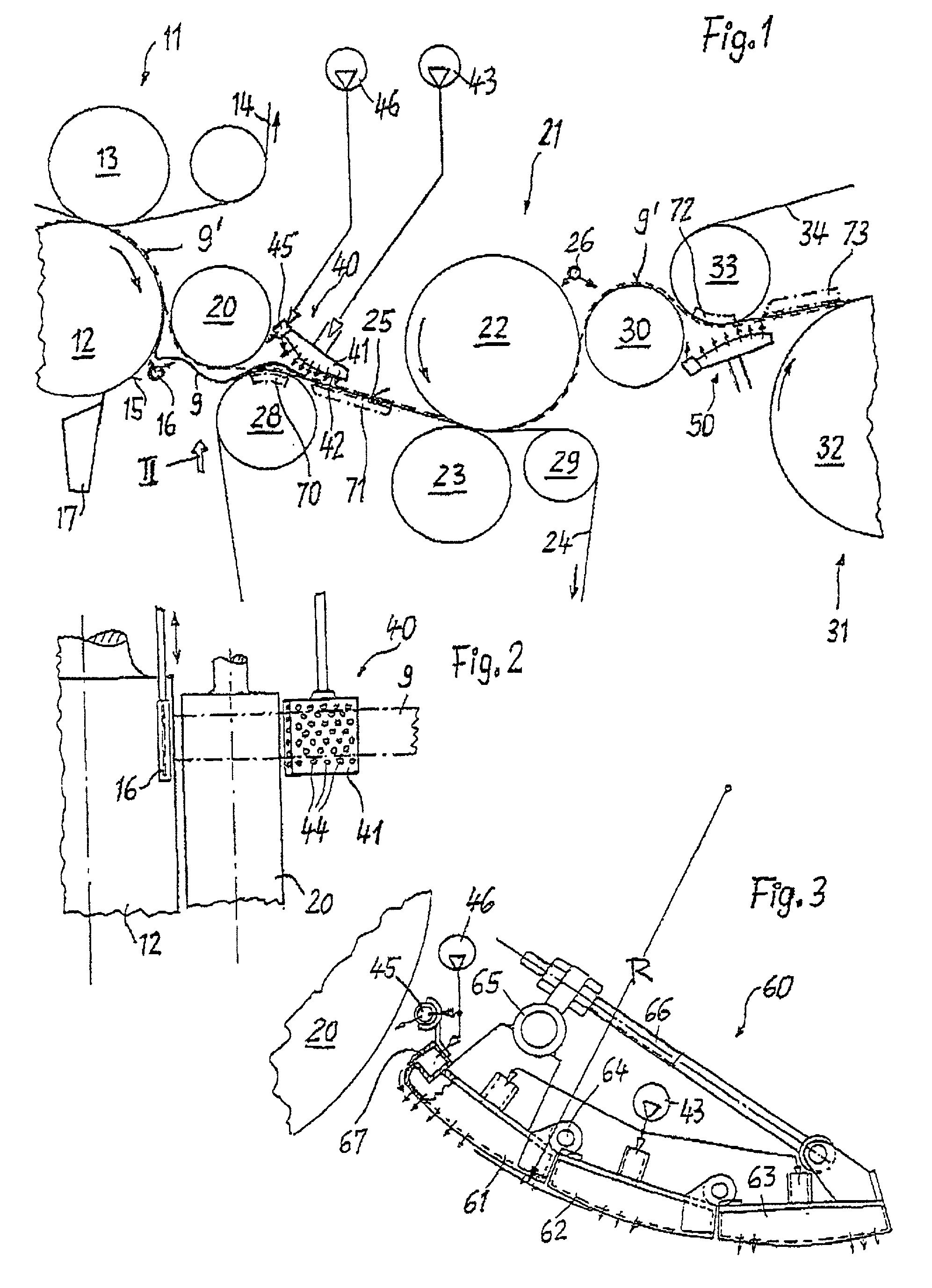
[0017] An air cushion is provided on the infeed area of the second traveling surface. The air cushion is created by an air table having a plurality of tiny orifices delivering air from an air plenum to the air cushion. According to the invention, the air cushion a created by a large number of tiny orifices which connect the air plenum to the air cushion and which are distributed substantially equally on the air table. This results in a significant advantage, namely that the oncoming tail (including its new beginning) is forced to lay on the second traveling surface with only a small amount of air moving with the second traveling surface. Therefore, the tail, which is running at the high machine speed together with the second traveling surface, is reliably pressed onto the second traveling surface. In other words, the air does not bounce off the second traveling surface and the tail is not lifted with the air. Such an undesirable behavior would result from creating an air cushion by use of a series of blast nozzles which deliver too much air at a too high pressure.
[0019] In summary, the method of the invention results in a very easy and reliable transfer of the tail so that the transfer does not need much operator skill. Also, the transfer works well with different paper grades and with different machine speeds including the high speed of modern paper machines.

Problems solved by technology

Thus, inexperienced personnel are able to start the threading operation without a lot of practice.

Method used


Image

  • Apparatus for the transfer of a lead strip of a paper web

Examples


Embodiment Construction

[0027] In FIG. 1, the normal path of a paper web to be dewatered in two presses 11 and 21 is shown as a broken line and designated 9'. Web 9' is traveling through the nip of a top-felted press 11 including a bottom press roll 12 (which directly contacts the web) and a top press roll 13 positioned in the loop of an endless dewatering felt 14. Bottom press roll 12 includes a (downwardly) "first traveling surface" 15. Close to it, a peeling jet device 16 and a conventional doctor 17 are arranged.

[0028] A subsequent dewatering press 21 is bottom felted. It includes a top press roll 22 (which directly contacts the web) and a bottom felt 24 guided by felt rolls 28 and 29, one (28) of which is positioned near the bottom press roll 12 of press 11. The part of felt 24 traveling from felt roll 28 to the nip of press 21 forms a so-called "second traveling surface" 25 including a so-called "infeed area" (positioned on felt roll 28) wherein the web comes into contact with felt 24. Web 9' is guid...


PUM


Abstract

An apparatus transfers a lead strip of a paper web, in particular the beginning of a still wet lead strip or tail, from a press roll of a paper-making machine to a following section of that machine. An air jet device peels off the beginning of the tail from the press roll and transfers it across a paper roll to an infeed area of a felt which guides the web into the following section. On an infeed area of the felt, an air cushion is created by an air table having a plurality of tiny holes delivering air from a low pressure plenum to the air cushion.

Description

BACKGROUND OF THE INVENTION[0001] 1. Field of the Invention[0002] The present invention relates to a method and apparatus for transferring a lead strip of a paper web from a first traveling surface (e.g., of a press roll or of a press belt) of a paper-making machine to a following section (e.g., a further wet press or drying section) of that machine. In particular, the beginning of a still wet lead strip (or "tail") is transferred according to the invention. This is to facilitate the threading of the paper web into the machine.[0003] 2. Description of the Related Art[0004] In a dewatering press section of a papermaking machine, as disclosed in FIG. 1 of U.S. Pat. No. 5,404,811, a still wet paper web 9 travels from a wire belt 8 of a forming section through three press nips 16 / 17, 1 / 2 and 2 / 3 and thereafter via a paper roll 59 to a further dewatering press 60; then the still wet web is transferred to a drying section (not shown). When the machine is started up or after a web break, t...

Claims


Application Information

Patent Timeline
Patent Type & Authority Applications(United States)
IPC IPC(8): D21F2/00D21G9/00
CPCD21G9/0063
Inventor MOHRSEN, LEIFBROOM, ALLAN
Owner VOITH PATENT GMBH
Learn More