Projection Lens and system

a technology applied in the field of projection lens and projection system, can solve the problems of revealing detrimental thermal effects, affecting the efficiency of production,

Inactive Publication Date: 2001-08-16
DUKE UNIV
View PDF0 Cites 21 Cited by
  • Summary
  • Abstract
  • Description
  • Claims
  • Application Information

AI Technical Summary

Problems solved by technology

Although a system may be small in size, however, its compactness may not necessarily be optimized.
However, aperture stops have previously been disadvantageously positioned within the physical confines of one of the lenses or other elements making up the projection lens.
Aspheres, although useful in limiting lens aberrations and in reducing lens size, can reveal detrimental thermal effects with high power light when positively powered optical elements are constructed of these materials.
A corresponding optical power change can result with high powered light, leading to performance deficiencies.

Method used


Image

  • Projection Lens and system
  • Projection Lens and system
  • Projection Lens and system

Examples


first embodiment

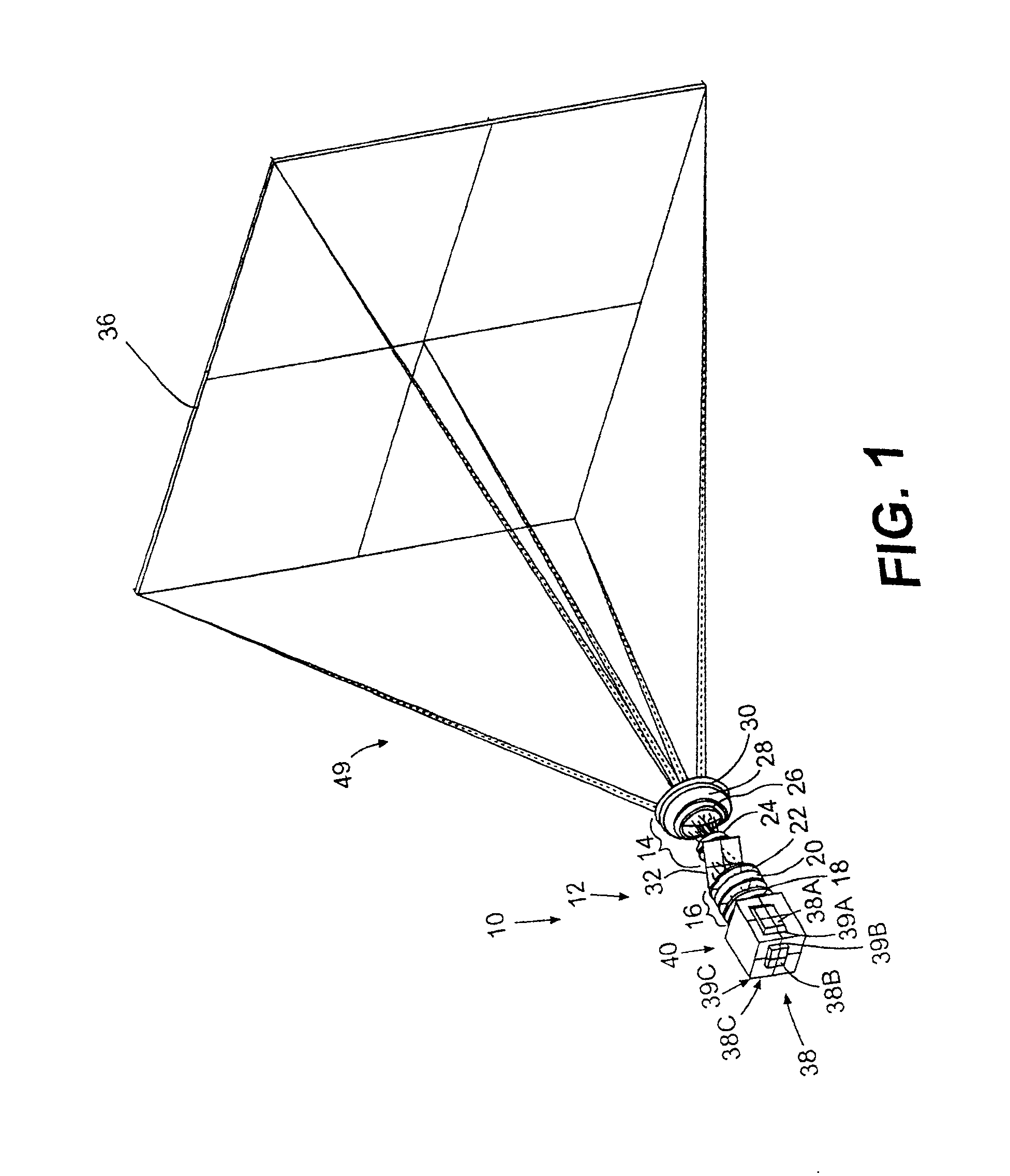
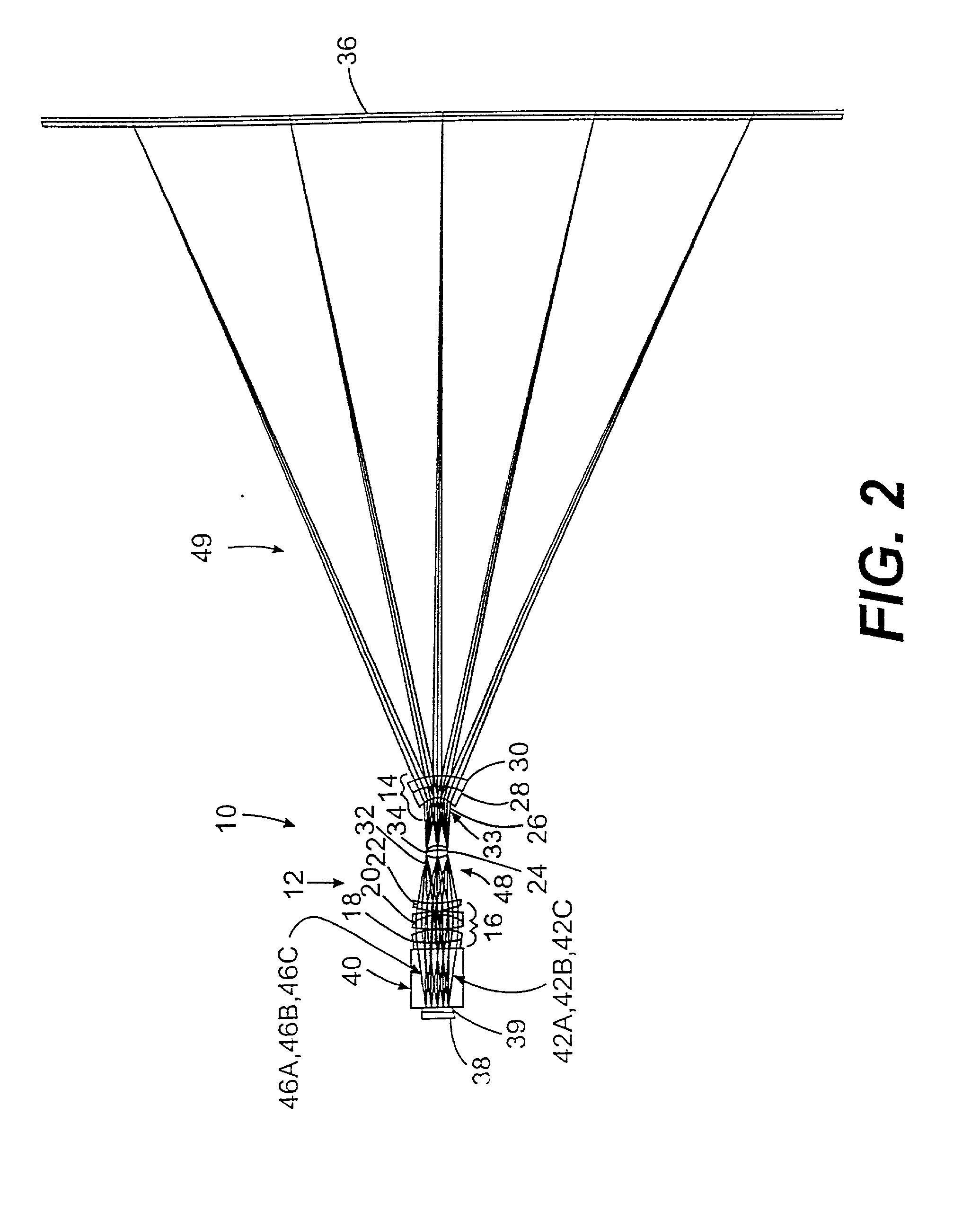
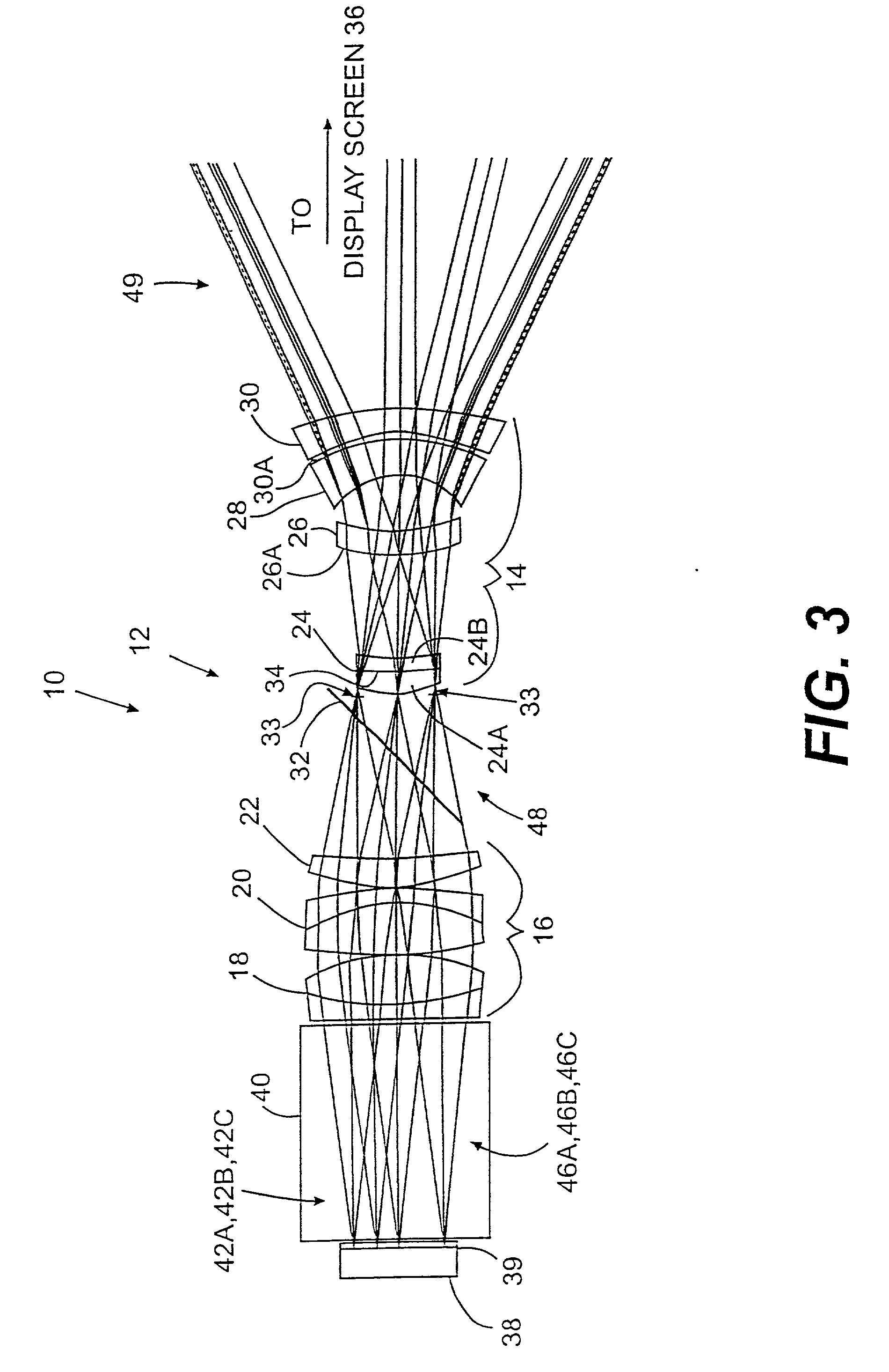
[0034] FIGS. 1-3 illustrate a reflection-based projection lens system 10 in accordance with the invention. The projection lens system 10 includes a projection lens 12 having a first or front lens unit 14 and a second or back lens unit 16. The front lens unit 14 and the back lens unit 16 are separated by an air gap. The front lens unit 14 has overall zero, near-zero or weak (e.g., negative) optical power with an angular magnification to project over a wide field of view. Other embodiments can have positive or negative optical powers for the front lens unit 14. The second lens unit 16 has overall positive optical power. In the exemplary embodiment shown in FIGS. 1-3, the second lens unit 16 includes lens elements 18, 20, and 22 and the first lens unit 14 includes lens elements 24, 26, 28, and 30. The lens elements 18, 20, 22, 24, and 26 are all positively powered lenses and the lens elements 28 and 30 are both negatively powered lenses. The lens elements 18, 20, and 24 may be doublets...

second embodiment

[0049] FIG. 5 shows a projection lens system 50 in accordance with the invention. The system 50 is similar to the projection lens system 10, and is a variation of the projection lens system 10. A projection lens 52 includes a front or first lens unit 14', which is similar to the lens unit 14 in the lens 12. The front lens unit 14' includes lens elements 24', 26', 28', and 30'. An optional clean-up element 34' can be sandwiched between lens elements 24A' and 24B' of which the lens element 24' is constructed. The front lens unit 14' also includes a remote aperture stop 33'. The elements 24' (24A' and 24B') 26', 28', 30', 33', and 34' are analogous or similar to the elements 24 (24A and 24B), 26, 28, 30, 33, and 34, respectively, in the projection lens 12. The system 50 further includes the imager 38 and the chromatic separator 40.

2TABLE 2 PROJECTIONS LENS SURFACE DATA SUMMARY Dwg. Element No. Surf No. Radius Thickness Glass / Material Diameter Conic 38 OBJECT AT Infinity 1.1 ZKN7 22.4 I...

third embodiment

[0055] FIG. 8 shows a projection system and an illumination subsystem in accordance with the invention. A light source 78B is similar to the light source 78A and includes a lamp 80B (similar to the lamp 80A) and a lightpipe (e.g., a tapered lightpipe or TLP) 82, which is a type of lightguide. The lamps 80A, 80B and the TLP 82 will be discussed further below. Like Table 1, Table 4 summarizes general projection lens 12, 52 data and illumination relay lens system 74 data for the embodiment shown in FIG. 8. Table 5 is a summary of the projection lens 12 (and 52) surface data for FIG. 8, in similarity to Table 2.

[0056] FIG. 8A associates the element surfaces in the second column of Table 5 with the numerical elements in the first column of Table 5 and shown in FIG. 8. Surfaces S13-S18 represent interior surfaces of the exemplary embodiment of the reflecting linear polarizer 32 and are not specifically identified in FIG. 8A, as similarly discussed above for FIG. 4A. No meaning should be a...


PUM


Abstract

Projection lenses and projection lens systems are telecentric between an illumination subsystem and a set of imagers. The lenses and systems can exhibit color fringing correction, uniform imager illumination, athermalization, and component articulation for improved imaging. The lenses and systems may be employed in display apparatuses, such as folded display apparatuses that have decreased footprint size, but long effective projection lengths.

Description

[0001] 1. Field of the Invention[0002] The present invention relates to projection lenses and projection systems, and, more particularly, to projection lenses and systems that provide improved use of the total light energy emitted by an illumination subsystem.[0003] 2. Description of Related Art[0004] Light projection is used to display images on large surfaces, such as large computer displays or television screens. In front projection systems, an image beam is projected from an image source onto the front side of a reflection-type, angle transforming screen, which reflects the light toward a viewer positioned in front of the screen. In rear projection systems, the image beam is projected onto the rear side of a transmission-type, angle transforming screen and transmitted toward a viewer located in front of the screen.[0005] In single exit pupil projection systems, three primary color images are projected through the same lens to form a full color image. These systems avoid color sh...

Claims


Application Information

Patent Timeline
Patent Type & Authority Applications(United States)
IPC IPC(8): G02B13/22G02B27/14H04N5/74H04N9/31
CPCG02B13/22G02B27/145H04N5/7408H04N9/3105H04N9/3197
Inventor TADIC-GALEB, BILJANAFISCHER, ROBERT E.
Owner DUKE UNIV
Why Eureka
Try Eureka