Rear window roll-up blind

a rear window and roll-up blind technology, applied in the direction of curtain accessories, curtain suspension devices, building components, etc., can solve the problem that the rear window roll-up blinds are not suitable for the rear window pane of station wagons and similar motor vehicles, and achieve the effect of stable guidance of blind materials

Inactive Publication Date: 2001-08-30
BOS
View PDF0 Cites 42 Cited by
  • Summary
  • Abstract
  • Description
  • Claims
  • Application Information

AI Technical Summary

Benefits of technology

0013] In the completely clamped-open or reeled-out state, the upper edge of the blind material can be received in hook-shaped pockets. These pockets prevent vibrations of the upper edge of the clamped-open blind material resulting from jolting of the vehicle. Such vibrations can also be largely avoided if the thrust members are aligned in such manner that the upper edge of the blind material slides on the inner side of the pane, because it is being pressed against the pane.
0014] A very stable guidance of the blind material is produced if the blind material is guided between two guide rails which run, proceeding from the winding shaft, in about the same direction. Since these guide rails do not run parallel to one another because of the rear window geometry, the blind material contains at least one tilt holder, which is adjustable in length. The tilt holder fits itself automatically to the changing distance between the guide rails.

Problems solved by technology

The known rear window roll-up blind is not suited for the rear window pane of station wagons and similar motor vehicles with a large rear shutter.

Method used


Image

  • Rear window roll-up blind
  • Rear window roll-up blind
  • Rear window roll-up blind

Examples


Embodiment Construction

[0032] In the following description of the figures terms such as "front", "rear", "above" or "below" as well as similar terms, inclusive of the terms "to the right" and "to the left", are used in the manner in which they are usually used for the designation of direction on a motor vehicle.

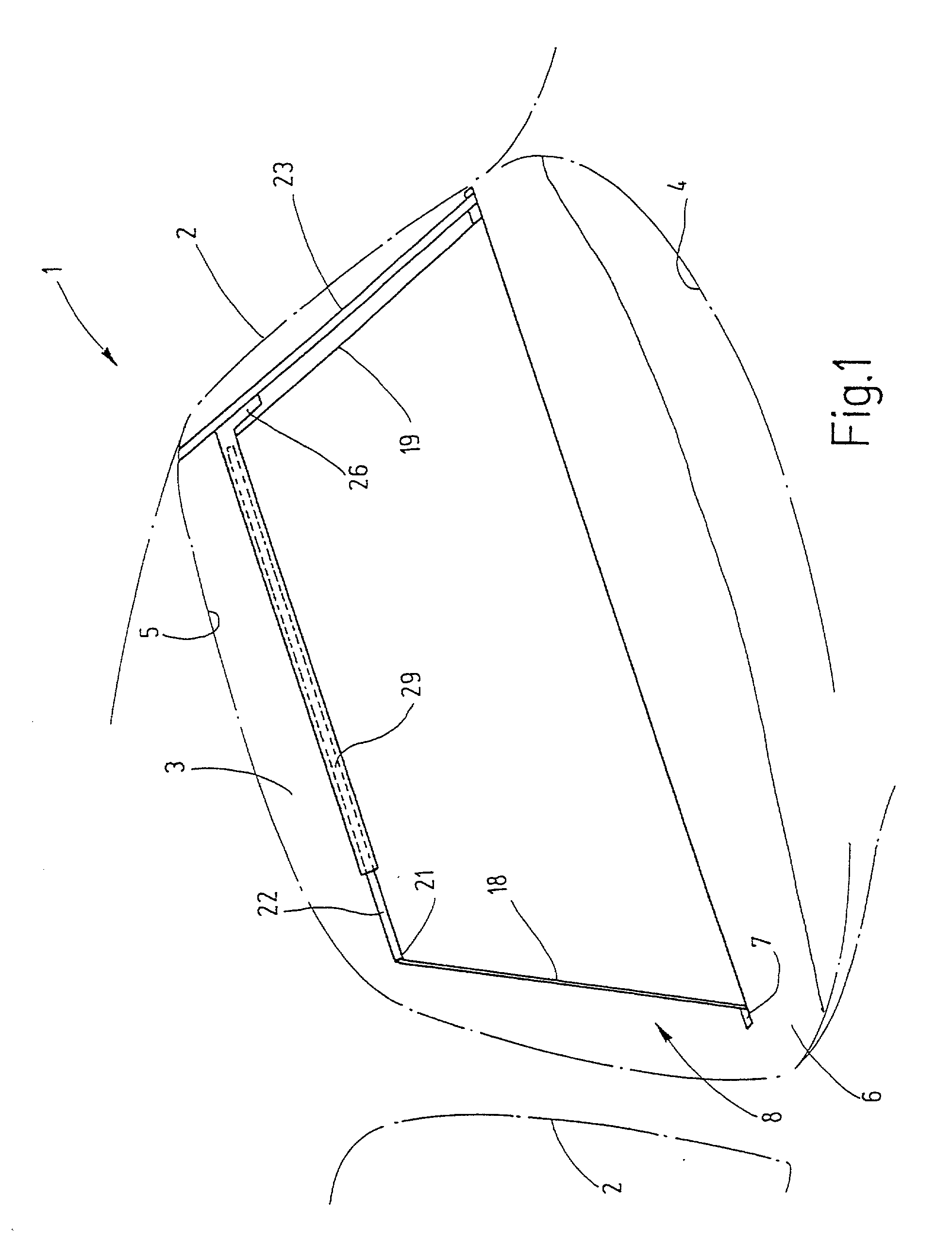
[0033] In FIG. 1, the rear portion of a motor vehicle 1 is schematically shown with a left and a right C-column. Between the C-columns, a rear window pane 3 extends from a lower edge 4 to a rear roof edge 5. In front of the rear window pane 3, a hat deposit area 6 is located which has a slot 7 running over its entire width. Further, a roll-up blind 8, which is shown in FIG. 1 in the reeled-out position, can be seen in the interior of the motor vehicle 1.

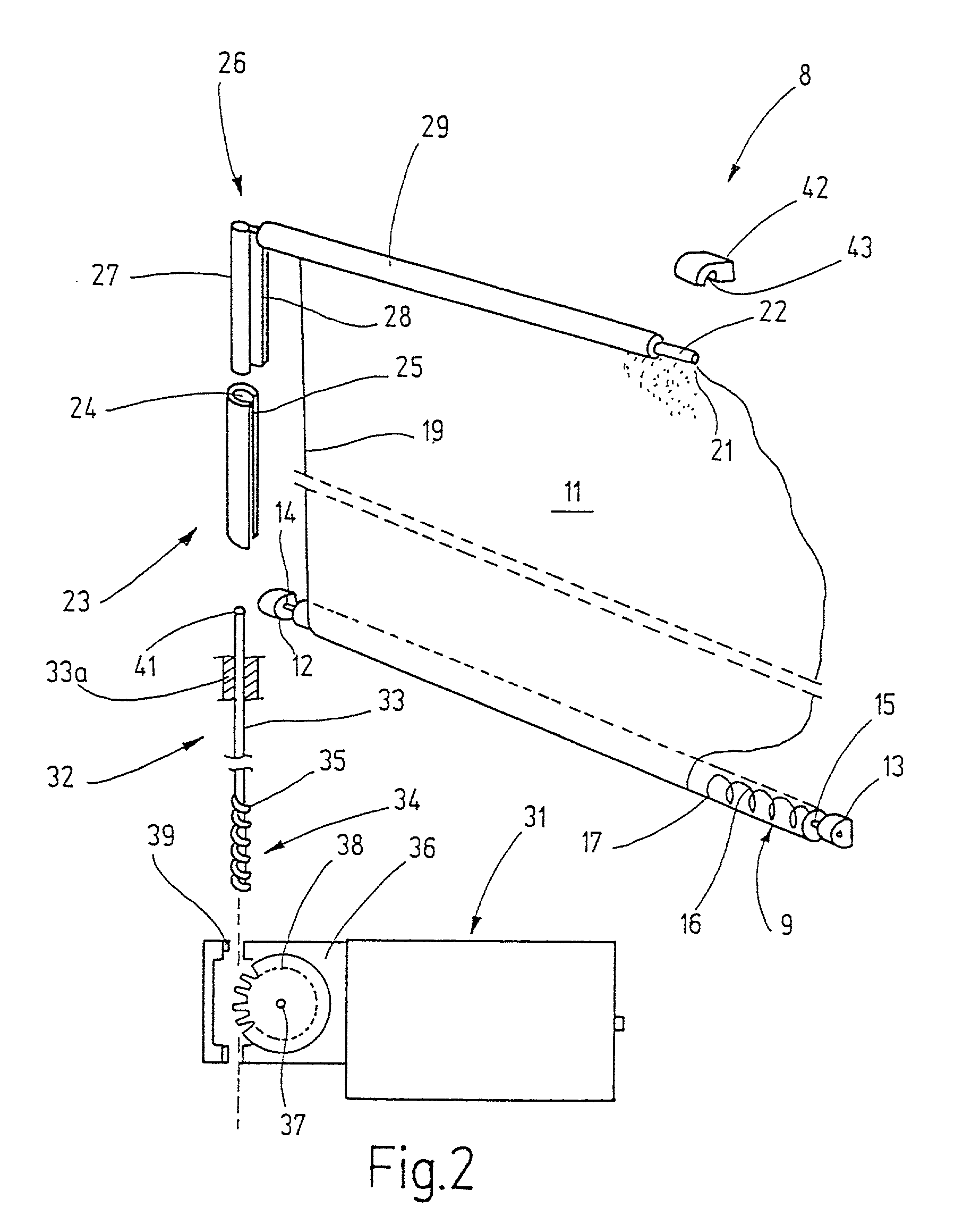
[0034] As shown in FIG. 2, the rear window roll-up blind 8 includes a winding shaft 9 which rotatably supported underneath the hat deposit area 6 and a blind material 11.

[0035] For supporting the winding shaft 9, bearing blocks 12 and 13 are provide...


PUM


Abstract

A rear window roll-up blind for motor vehicles is provided which has a winding shaft that is rotatably supported preferably under the hat deposit area. A blind material can be drawn through a slot in the hat deposit area out which covers the window (3). For this purpose, an actuating member engages on the edge of the blind material (11) that covers the greatest distance. The actuating member is a linear-form element which can be either tension-resistant or pressure-resistant. The blind material itself can be held clamped-open beside the window with the aid of at least one guide rail or one or two pressure- or bending-resistant actuating members.

Description

[0001] The invention generally relates to roll-up blinds for use in motor vehicles.[0002] A large number of solutions are known in order, with electrical remote control, to reel out and reel in a window roll-up blind arranged in the rear window pane of a passenger car.[0003] One solution, for example, is shown in EP-C-0 240 747, in which bending-resistant levers are used exclusively for the clamping-open of the blind. The known rear window roll-up blind has a base in which a winding shaft is rotatably supported. The winding shaft is pre-stressed in winding-up direction with the aid of a spring motor which is mounted with one edge on the winding shaft. The other edge is connected with a drawbar on which two one-armed levers engage that are borne on the base. The bearing axes of the levers run at a right angle to the winding shaft. On the drawing-up of the levers, the blind material is drawn off from the winding shaft.[0004] The known rear window roll-up blind is not suited for the re...

Claims


Application Information

Patent Timeline
Patent Type & Authority Applications(United States)
IPC IPC(8): E06B9/40B60J1/20B60J3/00E06B9/56E06B9/58E06B9/66E06B9/68
CPCB60J1/2027B60J1/2044B60J1/2052B60J1/2072B60J1/208B60J3/00
Inventor SCHLECHT, WERNER P.SEEL, HOLGERWALTER, HERBERT
Owner BOS
Why Eureka
Try Eureka