Self-locking nut

a self-locking and nut technology, applied in the direction of screws, load-modified fasteners, fastening means, etc., can solve the problems of large deviation in the tightening torque and difficulty in developing a practical nut, and achieve the effect of uniform shearing strength and easy machining of the crush section

Inactive Publication Date: 2001-08-30
KOYOKIZAI
View PDF0 Cites 26 Cited by
  • Summary
  • Abstract
  • Description
  • Claims
  • Application Information

AI Technical Summary

Benefits of technology

0008] The present invention thus provides a double nut type self-locking nut, the required tightening torque being provided by changing the shape of the cut out grooves in the main nut unit, thus allowing easy machining of the crush section. The crush section has a substantially ...

Problems solved by technology

With this kind of structure it is difficult to develop a practical nut because of the difficulty in manufacturing the loop-shaped groov...

Method used


Image

  • Self-locking nut
  • Self-locking nut
  • Self-locking nut

Examples


Embodiment Construction

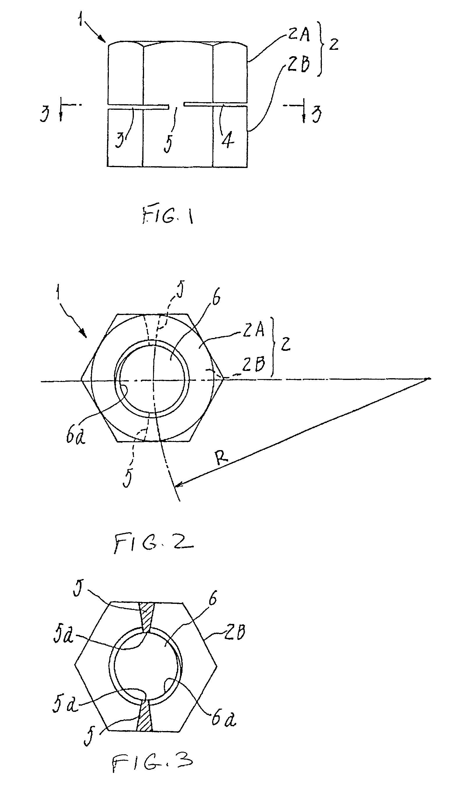
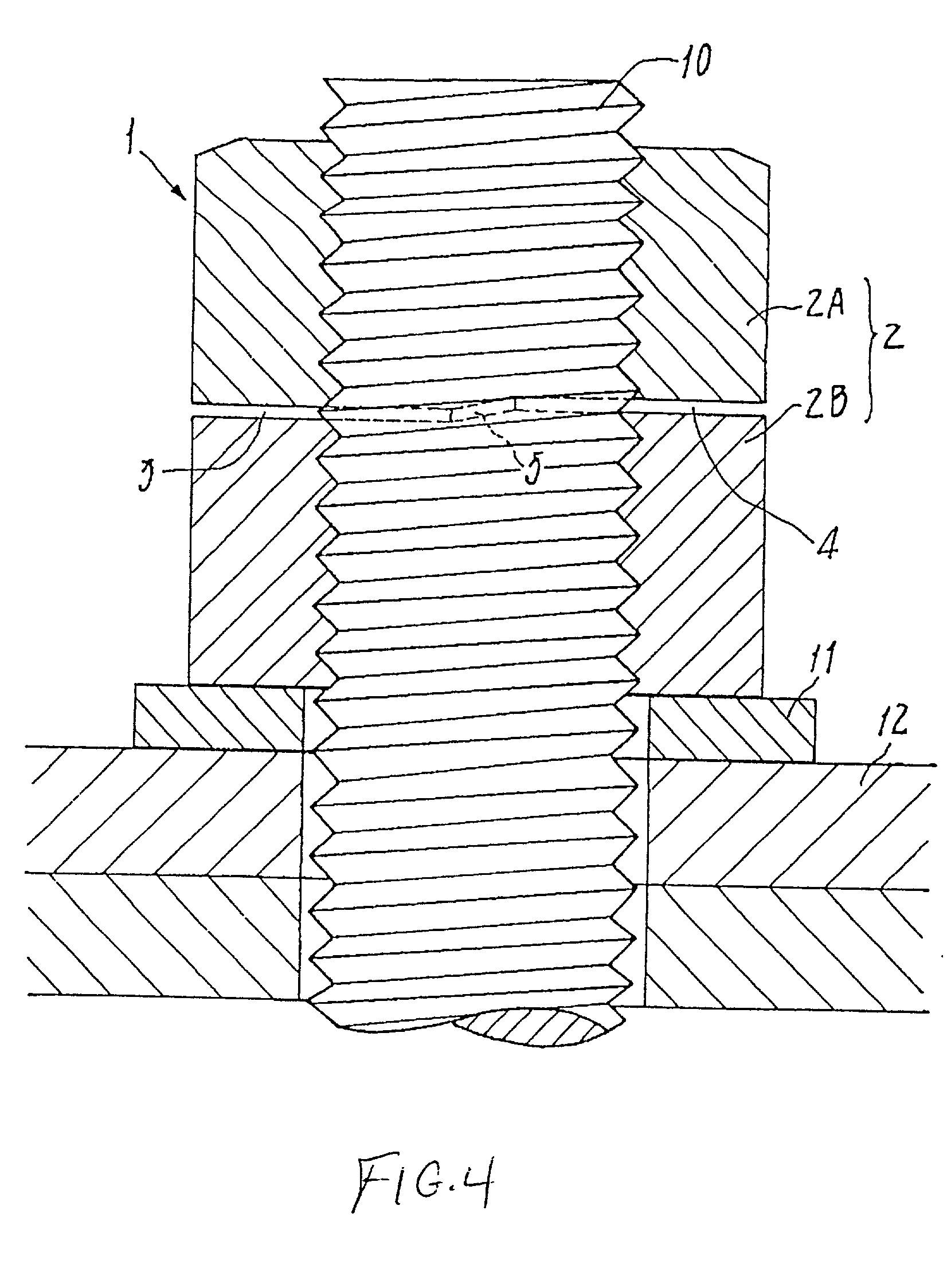
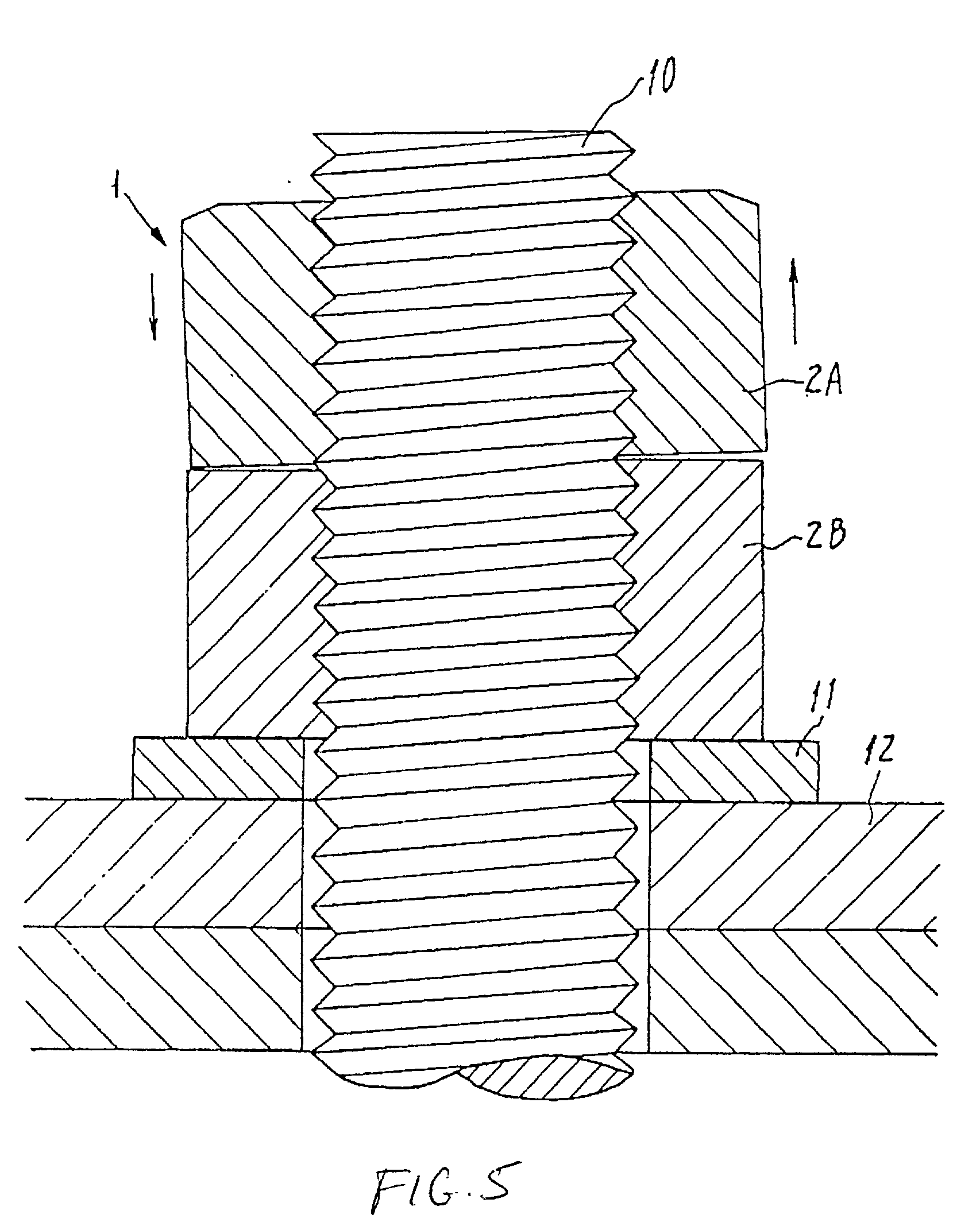
[0020] FIGS. 1-3 show self-locking nut 1 in accordance with the teachings of the present invention, nut 1 being longer than the conventional hexagonal nut. In the mid section of the main nut unit 2, a pair of cut out grooves 3 and 4 are cut opposing each other from the outer circumference surface to the axis core. The nut is separated into upper nut 2A and lower nut 2B, with both nuts 2A and 2B formed between cut out grooves 3 and 4, and mutually connected by two crush sections 5 that have oblong small cross sections stretching toward the radius direction. As shown in FIG. 1, cut out grooves 3 and 4 are placed so that they are slightly offset in the direction of the axis. Both grooves are placed on a flat surface directly intersecting the axis line of main nut unit 2. As it will be explained hereinafter, this enhances the locking effect. Specifically, in the event the measurement of main nut unit 2 is M12 and P1.5, the width of the cut out grooves 3 and 4 are approximately 0.5 mm an...


PUM


Abstract

A double nut type self-locking nut that lends to easy machining of a small cross section area of crush section with uniform cut out surface by changing the shape of the cut out grooves in the main nut unit in order to provide a stable level of tightening torque at a certain level of shearing strength.

Description

[0001] 1. Field of the Invention[0002] A self-locking nut that forms a small area of crush section by creating cut out grooves in the mid section of the nut to exert the effects of a double nut locking through two separated nuts whose aforementioned crush section has been sheared when a certain amount of tightening torque is applied on the nut.[0003] 2. Description of the Prior Art[0004] Prior art locking nuts are illustrated in FIGS. 7-9. In particular, FIGS. 7 and 8 illustrate a locking nut having loop-shaped grooves 23 and 24 placed opposite each other on the outer and inner circumference in the mid section of the main nut unit 22, forming a cylindrical crush section 25 of uniform thickness. With this kind of structure it is difficult to develop a practical nut because of the difficulty in manufacturing the loop-shaped groove 24, particularly in the inner circumference area.[0005] Referring to FIG. 9, the self-locking nut illustrated has loop groove 33 on the outer circumference ...

Claims


Application Information

Patent Timeline
IPC IPC(8): F16B31/02F16B39/12F16B39/28
CPCF16B31/021F16B39/12F16B39/28H04L63/1425
Inventor ITO, KATSUO
Owner KOYOKIZAI
Why Eureka
Try Eureka