Electrophotographic apparatus

a technology of electrophotography and apparatus, applied in the field of electrophotography apparatus, can solve the problems of erroneous addition of fringes, affecting the accuracy of electrophotography, and the upper limit of the effect of fringe control

Inactive Publication Date: 2001-10-18
HITACHI PRINTING SOLUTIONS LTD
View PDF0 Cites 9 Cited by
  • Summary
  • Abstract
  • Description
  • Claims
  • Application Information

AI Technical Summary

Problems solved by technology

When the fringe control is used, there arises a further problem in that a reverse electric field generated by the potential difference (the difference between the potential of an auxiliary exposure region and the intermediate potential) due to auxiliary exposure causes additional fringe-like erroneous printing.
Because of this consideration for a repulsive fringe, the effect of the fringe control has its upper limit, and there is a problem in that, even when primary and repulsive fringes are made equal in degree to each other, fringes sometimes occur according to the situation.
In the case where only one kind of the auxiliary exposure amount can be applied, the difference between the potential due to auxiliary exposure and the intermediate potential cannot be set to a very small degree (can be set to about one half of the difference between the latent image potential and the intermediate potential), and it may be therefore impossible to sufficiently suppress a repulsive fringe.
Therefore, such a control has a problem in that the number of parts, the size, and the cost of a circuit for the driver (hereinafter, such factors are referred to as the circuit scale) are increased.
In a case such as that where a semiconductor laser is used as the light emitting element and the process speed is high, particularly, a driver is required for each of the auxiliary exposure amounts, thereby producing a problem in that the circuit scale is largely increased.

Method used


Image

  • Electrophotographic apparatus
  • Electrophotographic apparatus
  • Electrophotographic apparatus

Examples


first embodiment

[0040] First Embodiment

[0041] A first embodiment of the invention will be described with reference to FIGS. 1 to 7.

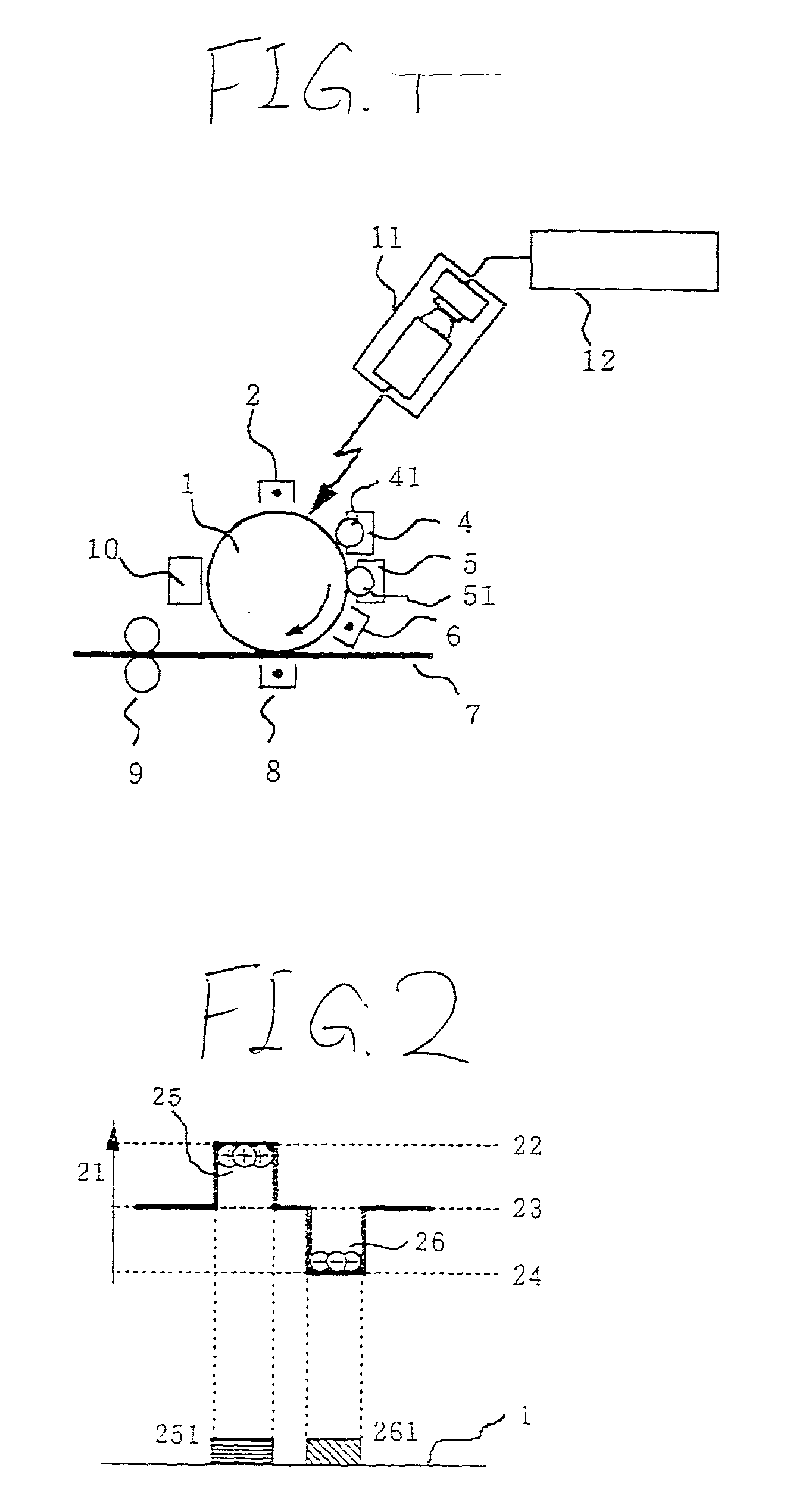
[0042] FIG. 1 is a sectional side view of a two-color laser printer using the potential dividing development method of the embodiment. The reference numeral 1 denotes a photosensitive drum (referred to also as a photosensitive member or a recording medium), 2 denotes a charger, 4 denotes a first developing unit, 41 denotes a developing roll of the first developing unit 4, 5 denotes a second developing unit, 51 denotes a developing roll of the second developing unit 5, 6 denotes a pre-transfer charger, 7 denotes a printing sheet (recording medium), 8 denotes a transfer unit, 9 denotes a fixing unit (fixing roller), 10 denotes a cleaner, 11 denotes an exposure unit, and 12 denotes an exposure controlling unit.

[0043] An electrostatic latent image is formed by the exposure unit 11 consisting of a semiconductor laser the light emission of which is controlled by the exposure ...

second embodiment

[0085] Second Embodiment

[0086] As another embodiment of the invention, an example of a laser printer in which a high-speed operation is not requested unlike the first embodiment described above is proposed. In the embodiment, in auxiliary exposure of an edge of a normal development image, the laser driver for forming the intermediate potential is used also as an auxiliary exposure unit for preventing fringe development from occurring. In auxiliary exposure of an edge of a reversal development image, the laser driver dedicated to auxiliary exposure or the laser driver for forming a reversal image may be used also as the auxiliary exposure unit (this will be described in the subsequent embodiment).

[0087] In the embodiment, the basic configuration and operation of the two-color laser printer using the potential dividing development method are identical with those of the two-color laser printer of Embodiment 1 shown in FIG. 1. However, the one-dot time is set to be longer than that in E...

third embodiment

[0091] Third Embodiment

[0092] As a further embodiment of the invention, an example of a laser printer in which a high speed operation of a laser printer is not requested (the one-dot time is 80 ns) as in the second embodiment is proposed. In the embodiment, in auxiliary exposure of an edge of a normal development image, the laser driver for forming the intermediate potential is used also as an auxiliary exposure unit for preventing fringe development from occurring, and, in auxiliary exposure of an edge of a reversal development image, the laser driver for forming a reversal image is used also as the auxiliary exposure unit.

[0093] In the embodiment also, the basic configuration and operation of the two-color laser printer using the potential dividing development method are identical with those of the embodiments described above, and the auxiliary exposure operation on a normal development image is identical with that of the second embodiment.

[0094] In the embodiment, a method is emp...


PUM


Abstract

In an electrophotographic apparatus, regions having at least three different potential levels Vc, Vw, and Vr are formed on a photosensitive member by using an exposing device, and developing processes respectively using colored particles of different kinds are performed by normal development and reversal development on two potential levels Vc and Vr excluding the intermediate potential level Vw. The apparatus has an auxiliary exposing unit for forming a fringe development preventing potential in an edge of an image forming region in order to prevent fringe development from occurring. The auxiliary exposing unit sets an auxiliary exposure amount by performing pulse-width modulation on a laser driver.

Description

[0001] 1. Field of the Invention[0002] The present invention relates to an electrophotographic apparatus (recording apparatus of an electrophotographic method) which is used in a printer, a facsimile apparatus, a copier, or the like, and more particularly to an electrophotographic apparatus of a potential dividing development method which is a development method wherein an image is developed by using colored particles such as a toner, and in which, as in the case of two-color printing, electrostatic latent images are formed with dividing the surface potential of a photosensitive member into plural levels (so-called potential division) and the electrostatic latent images are developed by toners of different colors that are oppositely charged.[0003] 2. Description of the Related Art[0004] A conventional development method and a potential dividing development method which are used in a conventional electrophotographic apparatus will be described.[0005] A recording apparatus using the e...

Claims


Application Information

Patent Timeline
Patent Type & Authority Applications(United States)
IPC IPC(8): G03G15/01G03G15/04G03G15/043B41J2/44H04N1/40
CPCG03G15/011G03G2215/0495H04N1/40037
Inventor MITSUYA, TERUAKIHOSHI, NOBUYOSHIOKADA, HISAOSANO, YOSHIHIKOAKATSU, SHINICHIKOBAYASHI, SHINYA
Owner HITACHI PRINTING SOLUTIONS LTD
Why Eureka
Try Eureka