Blower

a technology of blower and cylinder head, which is applied in the direction of positive displacement liquid engine, piston pump, liquid fuel engine, etc., can solve the problems of component electric insulation or dielectric strength impairment, and affect the insulating property

Inactive Publication Date: 2001-11-01
MINEBEA CO LTD
View PDF5 Cites 35 Cited by
  • Summary
  • Abstract
  • Description
  • Claims
  • Application Information

AI Technical Summary

Problems solved by technology

In this connection, there is a disadvantage that moisture, dirt, dusts, or other harmful gas or substance contained in the wind penetrate into the base of the motor to impair the insulating property of the electrical components such as printed circuit board 39 or electronic parts 38, i.e. these components are impaired in their electric insulation or dielectric strength.

Method used


Image

  • Blower
  • Blower
  • Blower

Examples


Embodiment Construction

[0024] An embodiment of the blower in accordance with the present invention will now be described in detail with reference to the concrete example thereof illustrated in the attached drawings.

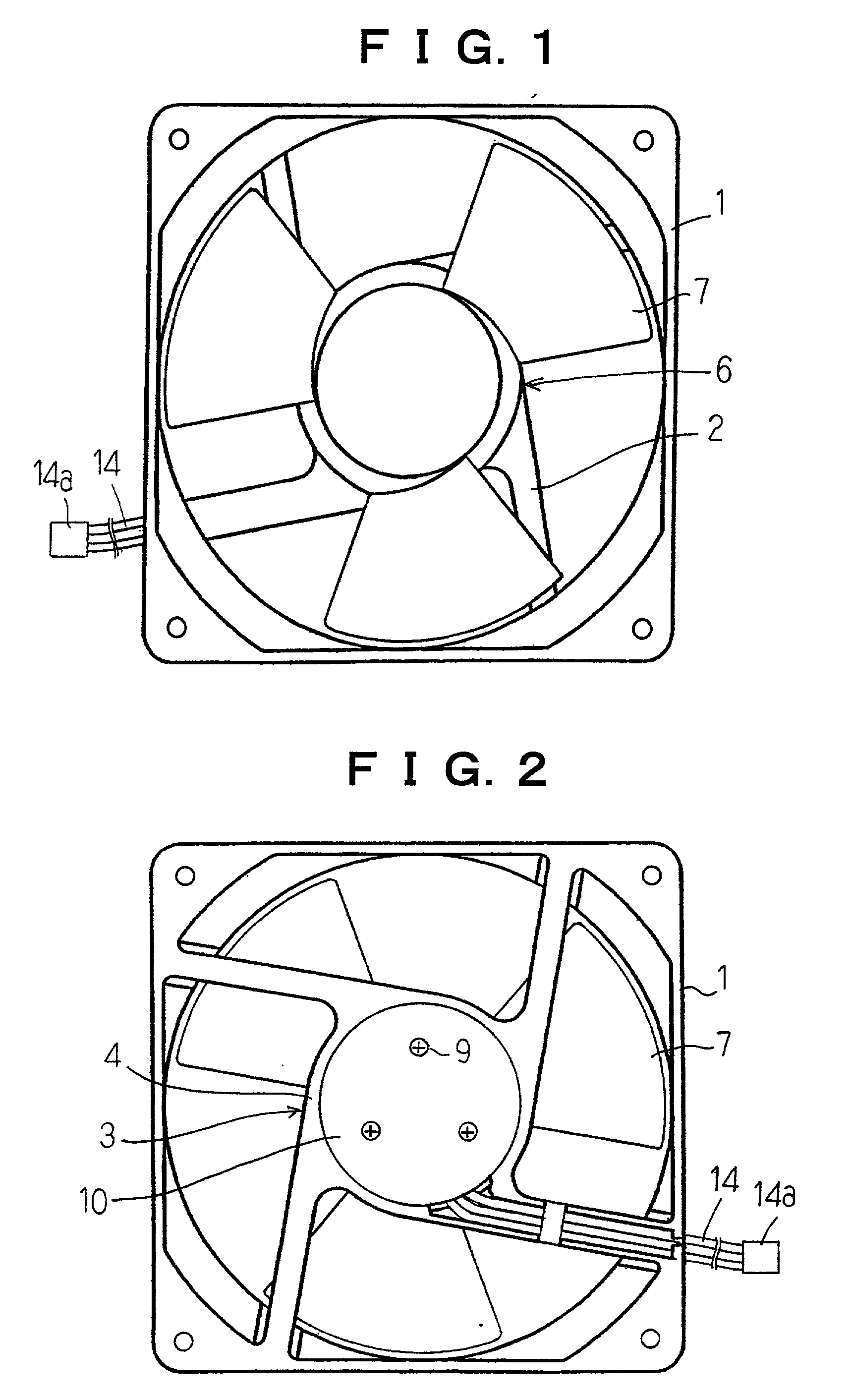
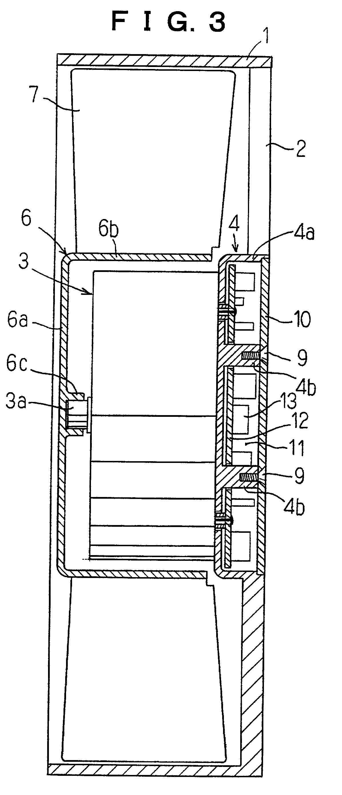
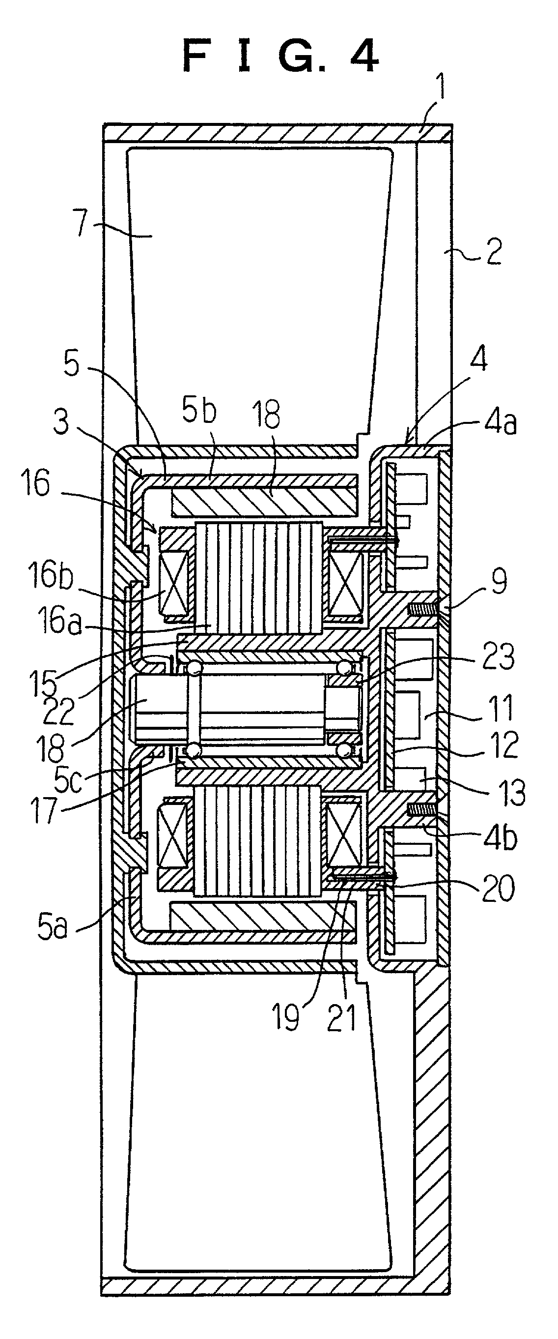
[0025] A blower body or a frame 1 of synthetic resin includes a base 4 supported integrally therewith at the central portion thereof through a few stays 2. A motor 3 is mounted on the front side of the base 4.

[0026] A distal end of a spindle shaft 3a of the motor 3 is fit and secured in a central hub 6c protruding backward from a front face plate 6a of an impeller 6. The impeller 6 includes the front face plate 6a, a flange 6b extending backward from the outer periphery of the plate, and a suitable number of blades 7 provided around the outer periphery of the flange.

[0027] The base 4 has a flange 4a extending backward from the outer periphery thereof to form a cylindrical body with a bottom having an opening at the rear end thereof. The cylindrical body is occluded by a cover 10 to define a sea...


PUM


Abstract

The object of the present invention is to provide a blower in which electrical components such as printed circuit board or electronic parts are isolated from the wind flowing through the blower to protect these components from moisture, dirt, dusts, or other harmful gas or substance contained in the wind, and to prevent the degradation of the insulating property such as the electric insulation or dielectric strength. A blower having an impeller 6 adapted to be rotated by means of a motor 3 comprises a base 4 for supporting the motor 3, the base is provided and supported at the central portion of a frame 1 through stays 2, a chamber 11 for accommodating electrical components formed in the base, the back portion of the chamber is adapted to be sealed by a removable cover 10, wherein the chamber for accommodating electrical components is formed by the base 4 having a flange 4a extending backward from the outer periphery thereof to form a cylindrical body with a bottom, the chamber has an opening at the rear thereof, and the rear opening of the base is occluded by the cover 10 detachably mounted by screws on the base 4.

Description

[0001] The present invention relates mainly to a blower suitable in the application for cooling office automation equipments.DESCRIPTION OF THE PRIOR ART[0002] The blower for cooling the office automation equipments has for example a structure as shown in FIG. 5 in which the blower includes a base 33 provided and supported at the central portion of a frame 31 by means of stays 32, a rotor member 35 rotatably journalled by means of a bearing apparatus 34 provided on the front side of the base at the central portion thereof, and an impeller 37 having a plurality of blades 36 provided on an outer peripheral flange 37a, the impeller is mounted on the rotor member 35.[0003] A printed circuit board 39 including electrical components 38 for controlling the motor is secured to an iron core holder 40a of a stator 40 by means of screws 41a, and is accommodated within a parts storing portion 42 surrounded by a flange 33a extending forward from the outer periphery of the base 33.[0004] The refe...

Claims


Application Information

Patent Timeline
Patent Type & Authority Applications(United States)
IPC IPC(8): F04D29/00F04D25/06F04D25/08F04D29/056F04D29/059F04D29/52H02K5/10H02K7/14H02K11/04
CPCF04D25/08H02K5/10H02K7/14H02K11/0073F04D25/0633H02K11/33
Inventor OBARA, RIKURO
Owner MINEBEA CO LTD
Why Eureka
Try Eureka