Protection plug

a technology of protection plugs and threads, applied in the direction of lubricating pumps, engine components, lubricant filling/draining, etc., can solve the problems of affecting the service life of the lubricating pump, so as to prevent damage to threaded components, the effect of quick and efficient inserting

a technology of protection plugs and threads, applied in the direction of lubricating pumps, engine components, lubricant filling/draining, etc., can solve the problems of affecting the service life of the lubricating pump, so as to prevent damage to threaded components, the effect of quick and efficient inserting

US20010052438A1Inactive Publication Date: 2001-12-20TUCKER ROBERT C

Image

  • Protection plug
  • Protection plug
  • Protection plug

Examples


Embodiment Construction

[0026] Illustrations of construction, design, and methods of operation of the invention are set forth below with specific references to the Figures. However, it is not the intention of the inventor that the scope of his invention be limited to these embodiments.

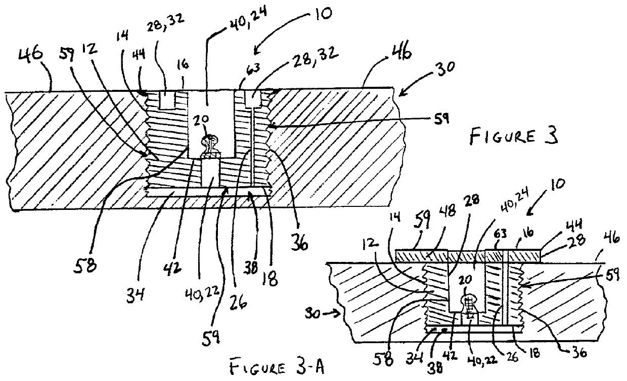
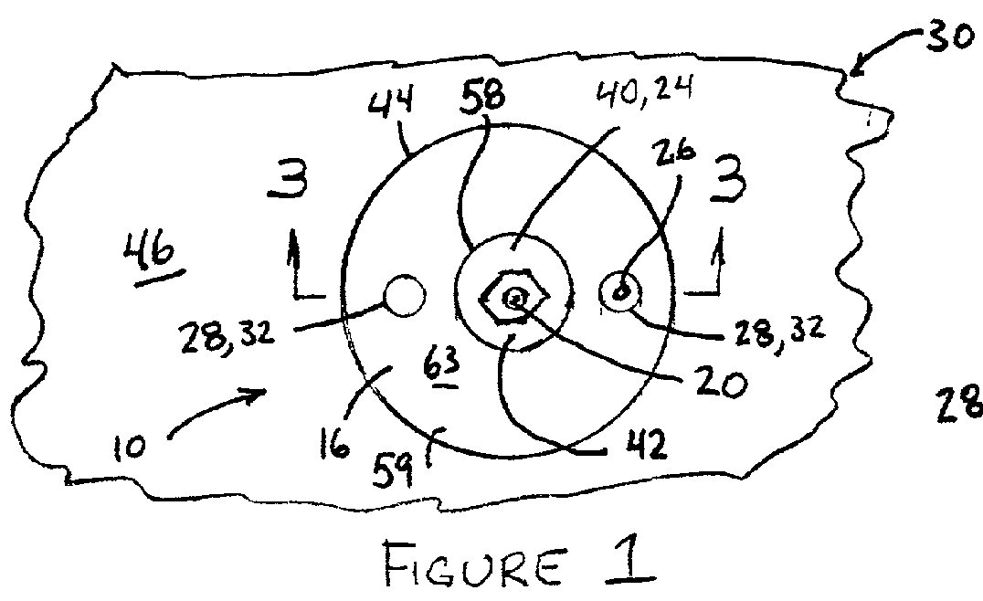
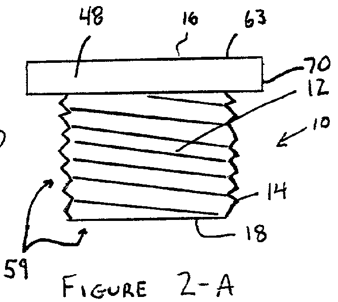
[0027] As shown in FIGS. 1, 1a, 1b, 2, and 2a, plug 10 has a substantially cylindrical body 12 with external threads 14, although body 12 need not be configured with external threads in embodiments comprising press-fitting type bodies. Body 12 and external threads 14 are configured to be insertable into a recessed area of a component 30 and to mate with an opposing internal surface, such as internal threads 36. As used herein, recessed area shall include, but is not limited to, areas below surface 46 in need of protection, such as the areas filled by plug 10 and the cavity 34 remaining below plug 10 shown in FIGS. 3 and 3a. Recessed areas also include areas extending through a component 30 such as bore 50 shown in FIGS. 4 and...


PUM


Abstract

A plug for protecting the interior of a recessed area of a component during storage is disclosed herein. The plug includes a lubrication fitting positioned thereon to flow a protective material, such as grease, into the cavity between the lower end of the plug and the recessed area and any remaining voids between the walls of the plug and the walls of the recessed area. The plug may also include an engagement surface to assist in the insertion and removal of the plug into and out of recessed areas of a component.

Description

[0001] 1. Field of the Invention[0002] This invention relates to devices for protecting internal areas of large cast or machined components, namely the internal threads.[0003] 2. Prior Art[0004] Large castings and machined components having internal threads are often placed outdoors for temporary storage. Accordingly, these components are subject to moisture and other damaging weather and environmental conditions. While many parts of the components do not suffer significant damage, the threads which are machined into metal surfaces often must be re-machined after the components have been exposed to the elements and damaged. Re-machining of threads significantly increases the turnaround time and is expensive, particularly in the case of leased equipment.[0005] In some instances, these components are temporarily stored outdoors and stacked on top of each other. If there are any protrusions that extend beyond the surfaces on which the components rest, the protrusions are broken or shea...

Claims


Application Information

Patent Timeline
20 Dec 2001
Publication
US20010052438A1
IPC
F16N21/06
CPC
F16N21/06
Inventors
SPENCER, R. WILSON