Image forming device

Inactive Publication Date: 2001-12-20
BROTHER KOGYO KK
View PDF0 Cites 21 Cited by
  • Summary
  • Abstract
  • Description
  • Claims
  • Application Information

AI Technical Summary

Problems solved by technology

This can result in a further positional shift between sheets from different trays.
This further positional shift is especially a problem when lower trays use the center registration supply method, because there is no reference plate to guide the sheets like in a sid

Method used


Image

  • Image forming device
  • Image forming device
  • Image forming device

Examples


Example

[0031] Next, a laser printer according to an embodiment of the present invention will be described while referring to the attached drawings.

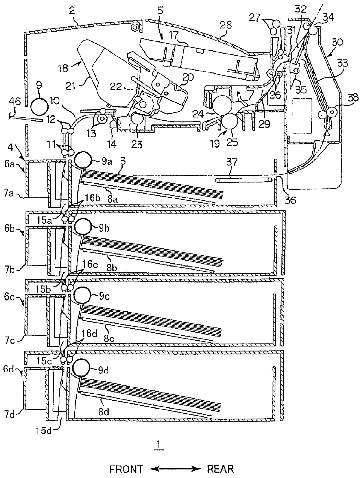
[0032] As shown in FIG. 1, the laser printer 1 includes a casing 2, a feeder unit 4, and an image forming unit 5. The feeder unit 4 and the image forming unit 5 are housed in the casing 2. The feeder unit 4 supplies sheets 3 to the image forming unit 5 and the image forming unit 5 forms images on the supplied sheets 3.

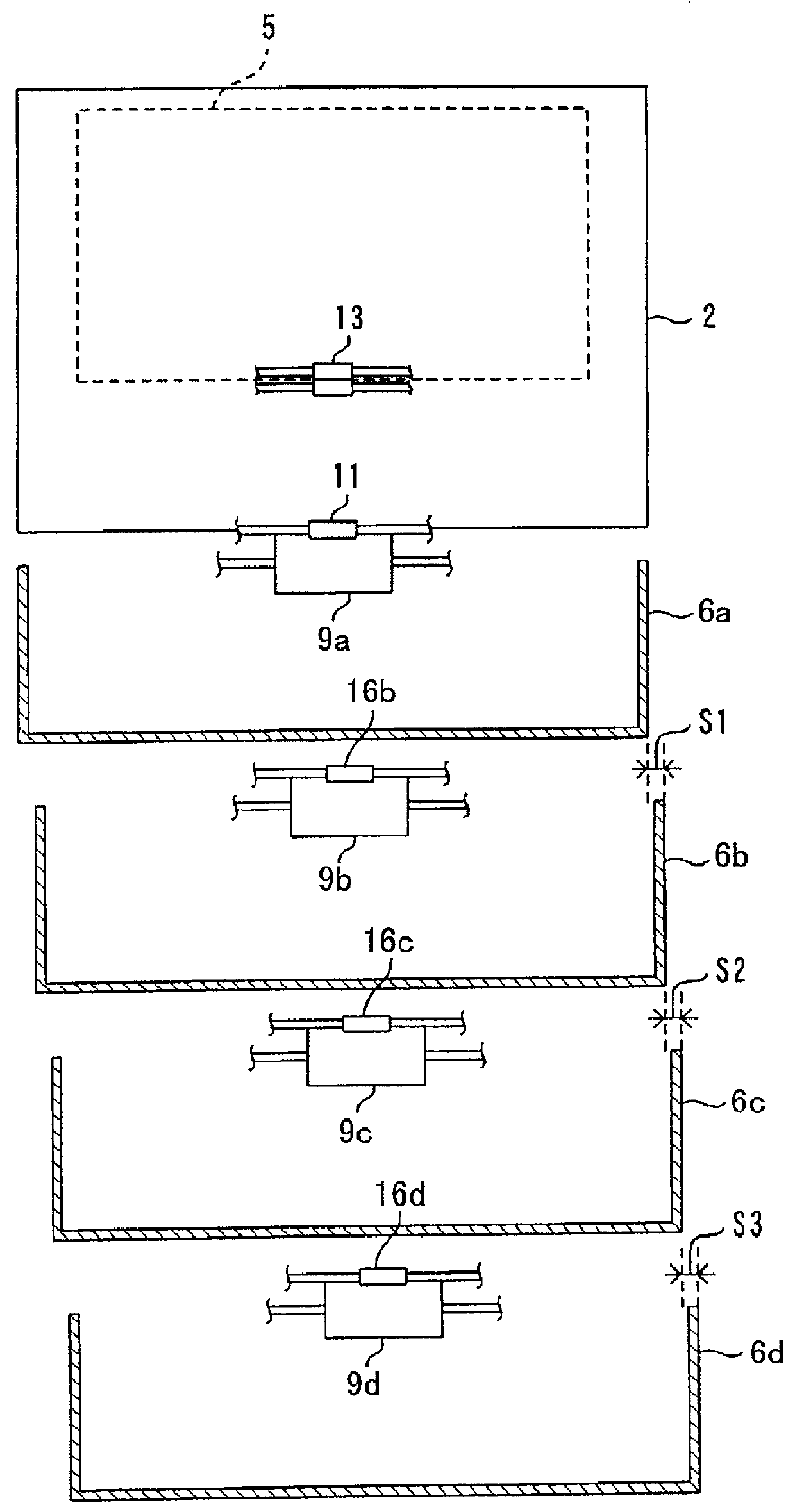
[0033] The feeder unit 4 includes a plurality of sheet supply trays 6a to 6d stacked vertically in a multi level configuration. That is, the sheet supply trays 6 include a standard tray 6a and lower trays 6b to 6d. The standard tray 6a is provided as a standard feature of the laser printer 1. The lower trays 6b to 6d are provided as options of the laser printer 1. The lower trays 6b to 6d are disposed in a stacked condition below the standard tray 6a.

[0034] The standard tray 6a is shaped like a box with an open upper surface. A gri...


PUM


Abstract

An image forming device includes a plurality of recording medium supply units, an offset amount memory, and a timing control unit. The recording medium supply units supply recording media. The offset amount memory stores an offset amount for each recording medium supply unit. Each offset amount is for compensating for positional shift in a recording medium supplied from a corresponding recording medium supply unit. The timing control unit retrieves, from offset amount memory, an offset amount corresponding to a presently used recording medium supply unit and performs image forming operations at a timing corrected by the retrieved offset amount.

Description

[0001] 1. Field of the Invention[0002] The present invention relates to an image forming device, such as a laser printer.[0003] 2. Description of the Related Art[0004] A laser printer outputs a laser beam based on image data and scans the laser beam across an electrically charged photosensitive drum at high speeds, to form an electrostatic to latent image on the photosensitive drum. Toner is supplied to the photosensitive drum to develop the electrostatic latent image into a visible toner image. The visible toner image is transferred onto a sheet interposed between the photosensitive drum and a transfer roller, thereby forming a toner image on the sheet based on the image data.[0005] Laser printers are provided with a standard sheet supply tray as a standard feature. The sheet standard supply tray holds a stack of sheets. Laser printers can often be provided with further sheet supply trays as an option, that is, in addition to the standard supply tray. The lower trays are stacked on...

Claims


Application Information

Patent Timeline
IPC IPC(8): B41J2/44B65H7/06G03G15/00G03G21/14H04N1/04H04N1/053H04N1/23
CPCG03G15/50G03G2215/00599H04N1/053H04N1/2353H04N2201/04786H04N2201/04793
Inventor ENDO, YOSHINORINOBE, HIROSHI
Owner BROTHER KOGYO KK
Why Eureka
Try Eureka