Heater control apparatus for exhaust gas sensor

a technology of exhaust gas sensor and control apparatus, which is applied in the direction of electric control, machines/engines, instruments, etc., can solve the problems of burning troubles of heaters or driving elements, the voltage of charging generators might increase, and the inability to avoid burning problems

Inactive Publication Date: 2002-01-03
MITSUBISHI ELECTRIC CORP
View PDF0 Cites 28 Cited by
  • Summary
  • Abstract
  • Description
  • Claims
  • Application Information

AI Technical Summary

Problems solved by technology

Particularly, in case that a state of connection between the battery and a charging generator for charging this battery became worse, a voltage of the charging generator might increase transiently and a relatively high voltage from this charging generator might be applied to the heater and in such a case, the burning troubles of the heater or the driving elements could not be avoided.

Method used


Image

  • Heater control apparatus for exhaust gas sensor
  • Heater control apparatus for exhaust gas sensor
  • Heater control apparatus for exhaust gas sensor

Examples


first embodiment

[0021] First Embodiment

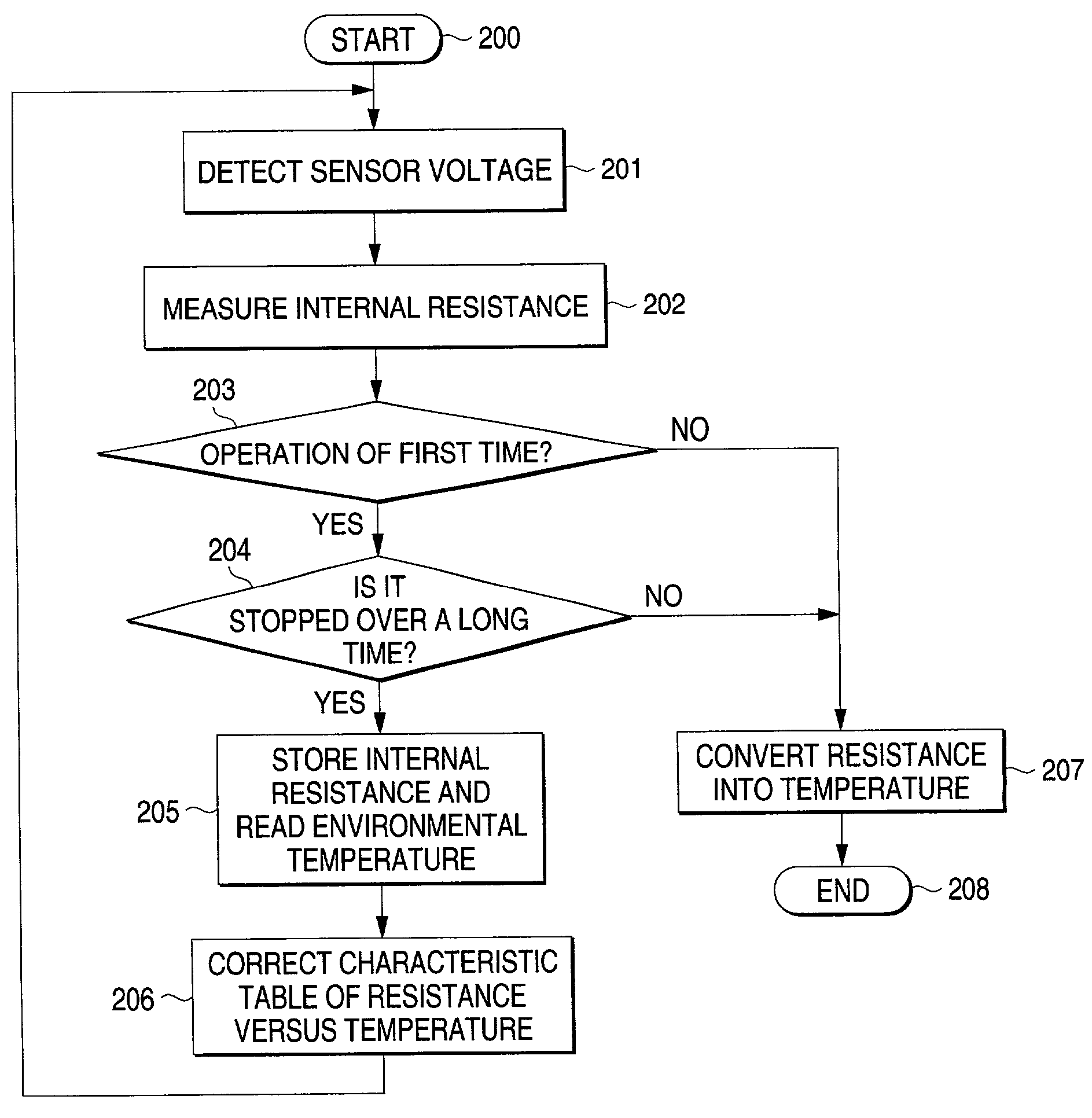
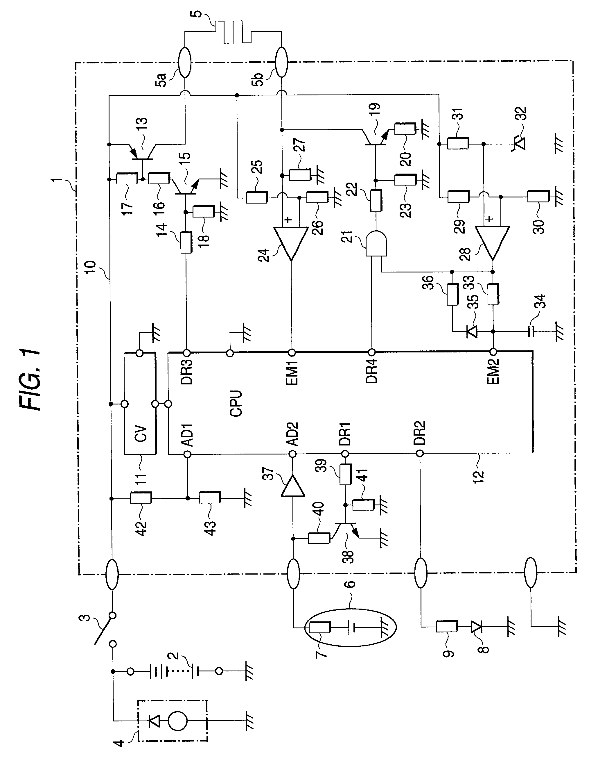
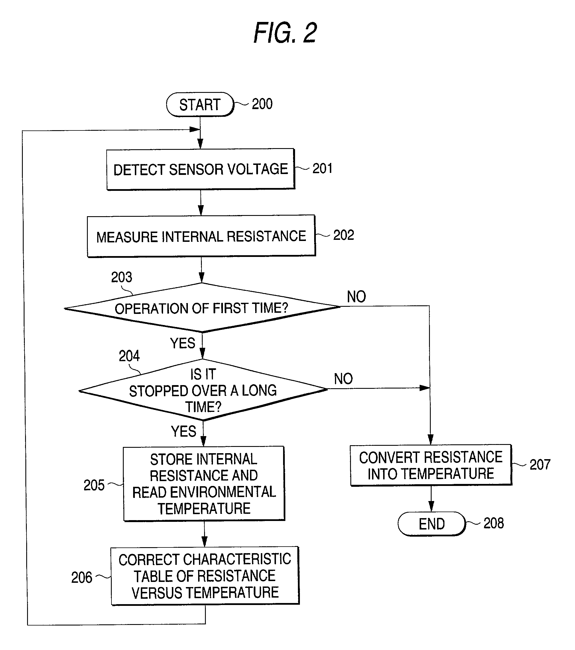
[0022] FIG. 1 is a circuit diagram of a heater control apparatus for exhaust gas sensor according to a first embodiment of the invention, and FIGS. 2 and 3 are flowcharts illustrating the operations. In FIG. 1, numeral 1 is a heater control apparatus, and numeral 2 is a battery for supplying electric power to the heater control apparatus 1 through a key switch 3, and numeral 4 is a charging generator for vehicle mounting for charging the battery 2, and numeral 5 is a heater controlled by the heater control apparatus 1, and numeral 6 is an exhaust gas sensor having an internal resistor 7 while being constructed so as to be integrated or closely placed with the heater 5 to be heated, and numeral 8 is a light emitting diode acting as display means driven by the heater control apparatus 1 through a resistor 9.

[0023] Numeral 10 is a power line within the heater control apparatus 1, and numeral 11 is a constant-voltage power source for supplying a constant voltage (...

second embodiment

[0038] Second Embodiment

[0039] FIG. 4 is a circuit diagram of a heater control apparatus for exhaust gas sensor according to a second embodiment of the invention, and FIG. 5 is a flowchart illustrating the operations, and like reference characters are given to the same parts as the first embodiment. In FIG. 4, numeral 50 is a heater control apparatus, and numeral 2 is a battery for supplying electric power to the heater control apparatus 50 through a key switch 3, and numeral 4 is a charging generator for vehicle mounting for charging the battery 2, and numeral 5 is a heater controlled by the heater control apparatus 50 and the heater 5 is integrated or closely placed with an exhaust gas sensor (not shown in FIG. 4). Numeral 8 is a light emitting diode acting as display means driven by the heater control apparatus 50 through a resistor 9.

[0040] Numeral 10 is a power line within the heater control apparatus 50, and numeral 11 is a constant-voltage power source for supplying a constan...


PUM

PropertyMeasurementUnit
constant voltageaaaaaaaaaa
concentrationaaaaaaaaaa
temperatureaaaaaaaaaa

Abstract

The heater control apparatus comprises an exhaust gas sensor 6 for detecting an oxygen concentration in exhaust gases of an internal combustion engine, a heater 5 for heating this exhaust gas sensor 6 to a predetermined temperature, a power source including a battery 2 for supplying electric power to this heater 5 and a charging generator 4 for charging this battery 2, a switching element 19 inserted into a circuit for supplying electric power to the heater 5 from the power source, control means 12 for performing current-carrying control of the switching element 19 so as to maintain a temperature of the exhaust gas sensor 6 at a predetermined value, and an overvoltage detection element 28 for outputting an abnormal detection signal when a voltage of the power source exceeds a predetermined value, and it is constructed so that the switching element 19 is broken to stop the passage of current to the heater 5 by the abnormal detection signal of the overvoltage detection element 28 when a voltage of the charging generator 4 abnormally increases due to disconnection etc. of the battery 2 of the power source.

Description

[0001] 1. Field of the Invention[0002] This invention relates to a heater control apparatus for oxygen concentration sensor heating for detecting an oxygen concentration contained in exhaust gases of an internal combustion engine.[0003] 2. Description of the Related Art[0004] A technique for making purification of the exhaust gases and improvements in fuel consumption by detecting the oxygen concentration contained in the exhaust gases of the internal combustion engine and performing feedback control on an air-fuel ratio of an air-fuel mixture supplied to the internal combustion engine in response to the detected oxygen concentration is well known, and the technique is widely used in the internal combustion engine for vehicle. An exhaust gas sensor for detecting the oxygen concentration needs to stabilize detection characteristics of the oxygen concentration by maintaining a temperature at an activation region and for this purpose, a heater control apparatus for passing a current th...

Claims


Application Information

Patent Timeline
Patent Type & Authority Applications(United States)
IPC IPC(8): G01N27/409F02D41/22F02D45/00G01N27/12G01N27/406H05B1/02
CPCG01N27/122G01N27/4067H05B1/0236
Inventor HASHIMOTO, KOHJINAKAMOTO, KATSUYA
Owner MITSUBISHI ELECTRIC CORP
Why Eureka
Try Eureka