LED sign

a technology of led signs and led lights, applied in the field of led signs, can solve the problems of large heat emission, limited display or display signs, complex and effective illumination signs, etc., and achieve the effects of simple and inexpensive design, operation, and long life cycl

Inactive Publication Date: 2002-01-17
E P SURVIVORS
View PDF0 Cites 115 Cited by
  • Summary
  • Abstract
  • Description
  • Claims
  • Application Information

AI Technical Summary

Benefits of technology

0030] A principal advantage of the present invention is that the LED sign is capable of producing several different types, patterns and / or combinations of light signals, images, characters and / or messages.
0031] Another principal advantage of the present invention is to be rugged and to have a relatively longer life cycle than traditional signs.
0032] Still another principal advantage of the present invention is to produce a truer or pure light output color for a sign without the use of filters.
0033] Still another principal advantage of the present invention is to allow the user to adjust the color of the image, character and / or message without having to make a physical adjustment to the LED sign.
0034] Still another principal advantage of the present invention is that it may be formed into various sizes. This allows the invention to be customized for the particular need.
0035] Still another principal advantage of the present invention is the provision of an LED sign which is formed of a relatively simple and inexpensive design, construction, and operation and which fulfills the intended purpose without fear of failure or risk of injury to persons and / or damage to property.

Problems solved by technology

Such displays or signs are limited in that they may be seen from essentially only one direction.
As lighting technology has advanced so to has the complexity and effectiveness of illuminated signs.
These types of lamps emit significant quantities of heat which may be difficult to dissipate from a sealed display, sign or fixture and may damage electronic circuitry contained therein.
In addition, these lamps consume large amounts of current requiring a large power supply, battery or electrical source.
These lamps also generate substantial electromagnetic emissions which may interfere with radio communications, which may be especially problematic in vehicle mounted lamps and displays.
Finally, these lamps, are typically not rugged and generally have a relatively short operational life necessitating frequent replacement.
Another problem with the known signs is the use of filters to produce a desired color.
Furthermore, filters fade or flake over time rendering the filters unable to consistently produce a desired color for observation in an emergency situation.
These problems associated with traditional signs are exacerbated by the fact that creating multiple light signals or images may require multiple signs.
Further, there is little flexibility in modifying an existing sign which may be cost prohibitive.
The known signs also fail to have flexibility for the provision of variable intensity for the sign light sources.
The number of available distinct and independent visual light effects is therefore limited.
Remote control of a sign is generally undesirable because radio frequency transmitters and receivers are generally costly and require a large power supply which is a concern for motor vehicles.
Further, it has not been know to use a variable and / or pulsating light signal or SIT-TEL communications as generated from a sign through the use of LED technology.
Currently each year a significant number of automobiles and other motor vehicles are involved in accidents areas which are not marked with warning bells, and / or flashing light signals.
The absence of warning devices is frequently the result of economic considerations at remote and / or low traffic areas.

Method used


Image

  • LED sign
  • LED sign
  • LED sign

Examples


Embodiment Construction

is hereafter described with specific reference being made to the drawings in which:

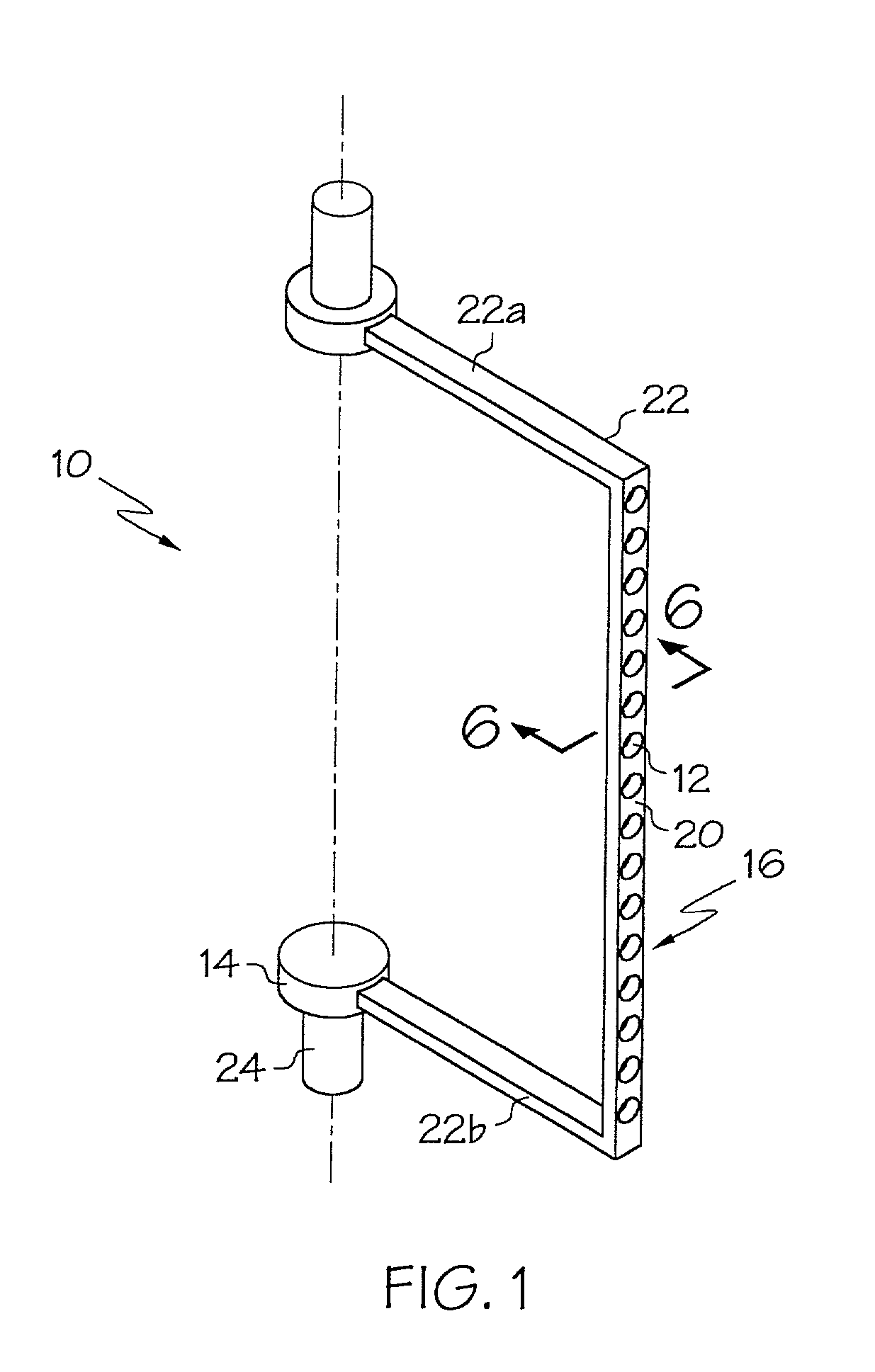
[0066] FIG. 1 is a perspective view of an embodiment of the invention wherein a single display is equipped with a single arm and single column of light sources.

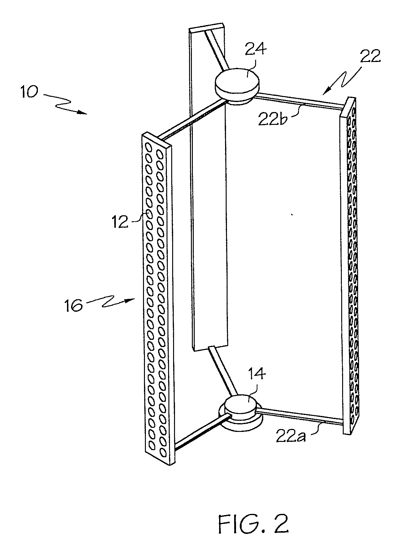
[0067] FIG. 2 is a perspective view of an embodiment of the invention wherein a single display is equipped with a plurality of arms and columns of light sources.

[0068] FIG. 3 is a perspective view of an embodiment of the inventive display system which includes a plurality of multi-armed displays arranged in a circular pattern.

[0069] FIG. 4 is a perspective view of another embodiment of the inventive display system which includes a plurality of multi-armed displays arranged in a linear arrangement.

[0070] FIG. 5 is a perspective view of another embodiment of the inventive display system which includes a plurality of multi-armed displays arranged in both a linear and circular pattern.

[0071] FIG. 6 is a close-up perspective view of an individual li...


PUM


Abstract

A system for displaying an image comprising at least one display apparatus. Each display apparatus including at least one light bar having a plurality of light emitting diodes mounted thereto. At least one support joining each light bar to a rotation mechanism. The rotation mechanism being constructed and arranged to rotate the light bars at a predetermined rate of rotation. The system also includes a controller in electrical communication with each of the plurality of light emitting diodes, and the rotation mechanism of each of the at least one display apparatus. The controller constructed and arranged to control the predetermined rate of rotation and selectively activate the light emitting diodes to produce at least one image capable of being perceived by a viewer.

Description

[0001] This application claims priority from U.S. provisional application No. 60 / 204,612, filed May 16, 2000, the entire contents of which are incorporated herein by reference. This application also claims priority from U.S. Provisional application No. 60 / 248,894, filed Nov. 15, 2000. The entire contents of which are incorporated herein by reference.[0002] Not Applicable[0003] 1. Field of the Invention[0004] The present invention is directed to an apparatus having a plurality of multi-colored light emitting diodes (LEDs) arranged on one or more vertically extending arms or light sticks. The light sticks are mounted on one or more supports which are dispersed about a rotation point. The apparatus includes a controller which is constructed and arranged to selectively control the speed of rotation of the support(s) as well as the illumination of the individual LEDs positioned within each vertically extending arm. The controller provides for selective rotation of the support and illumin...

Claims


Application Information

Patent Timeline
Patent Type & Authority Applications(United States)
IPC IPC(8): B60Q1/26G09F9/33G09G3/00G09G3/32
CPCB60Q1/2611B60Q2900/30G09F9/33G09G3/005B64D2203/00
Inventor PEDERSON, JOHN C.
Owner E P SURVIVORS
Why Eureka
Try Eureka